Serial Receive
R2026bSerial Receive block
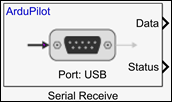
To add a block to a model, double-click the canvas and start typing the block name. Then, select the block from the list.
Libraries:
UAV Toolbox Support Package for ArduPilot Autopilots /
Peripheral Blocks
Description
Add-On Required: This feature requires the UAV Toolbox Support Package for ArduPilot Autopilots add-on.
The Serial Receive block receives data from a selected ArduPilot® serial communication interface (SCI) port. The block outputs the received values as an N-by-1 array.
Use this block when your model needs to receive serial data from ArduPilot supported hardware and process that data within a Simulink® workflow.
The Serial Receive block is supported only on ArduPilot based flight controllers. The block is not supported for SITL board configuration or ArduPilot Host Target autopilot configuration.
Note
When you use this block to receive serial data, set the SERIALx_PROTOCOL parameter of the ArduPilot autopilot to an unused protocol value. For instance, using Mission Planner, set the parameter to 55. When SERIALx_PROTOCOL has its default value, ArduPilot assigns a built-in driver to the port and the serial block cannot access it.
Examples
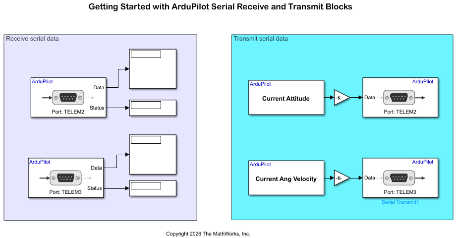
Getting Started with ArduPilot Serial Receive and Transmit Blocks
Configure two ArduPilot® telemetry ports for bidirectional loopback communication using Serial Transmit and Serial Receive blocks in Simulink®.
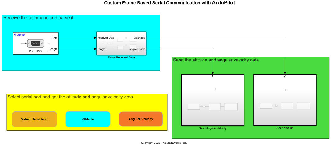
Send and Receive Custom Frame-Based Serial Data with ArduPilot
Send and receive custom frame-based serial data between a host computer and an ArduPilot® flight controller using the UAV Toolbox Support Package for ArduPilot Autopilots®. The example uses a request-response protocol in which a MATLAB® script on the host computer sends a data request, and the flight controller responds with the requested attitude or angular velocity data.
Ports
Output
Parameters
Select the serial port that the block uses to communicate between the target hardware and the external serial device. The available options depend on the serial port labels supported by the target hardware configuration. To verify the mapping between the logical port name and the physical port label, check the hardware board configuration set.
The selected serial port is supported only when you build and deploy the model to hardware. In Monitor & Tune(external mode) or Connected IO, the USB is reserved for communication between Simulink and the target hardware and cannot be used by this block.
Dependencies
To enable this parameter, disable the Select logical serial port parameter.
Programmatic Use
To set the block parameter value programmatically, use
the set_param (Simulink) function.
| Parameter: | SerialPortLabel |
| Values: | USB | TELEM1 | TELEM2 | TELEM3 | GPS1 | GPS2 | GPS | GPS MODULE | UART4 & I2CB
|
| Data Types: | string | char |
When you select this parameter, the Serial logical port parameter becomes available.
Programmatic Use
To set the block parameter value programmatically, use
the set_param (Simulink) function.
| Parameter: | SelectLogicalPort |
| Values: | off | on |
| Data Types: | string | char |
Select the logical serial port. The logical port name maps to a numeric SCI module. In Monitor & Tune(external mode) or Connected IO, the USB is reserved for communication between Simulink and the target hardware and cannot be used by this block.
Dependencies
To enable this parameter, select the Select logical serial port parameter.
Programmatic Use
To set the block parameter value programmatically, use
the set_param (Simulink) function.
| Parameter: | LogicalPortList |
| Values: | Serial 0 (default) | Serial 1 | Serial 2 | Serial 3 | Serial 4 | Serial 5 | Serial 6 | Serial 7 | Serial 8 |
| Data Types: | string | char |
Select the data type of the received data.
Programmatic Use
To set the block parameter value programmatically, use
the set_param (Simulink) function.
| Parameter: | DataType |
| Values: | uint8 (default) | int8 | uint16 | int16 | uint32 | int32 | single | double |
| Data Types: | numeric |
Select this parameter to enable the Length port, which outputs the number of received elements.
Programmatic Use
To set the block parameter value programmatically, use
the set_param (Simulink) function.
| Parameter: | PartialData |
| Values: | off (default) | on |
| Data Types: | string | char |
Specify the number of bytes to receive at each sample time.
Programmatic Use
To set the block parameter value programmatically, use
the set_param (Simulink) function.
| Parameter: | DataLength |
| Values: | 1 (default) | any integer greater than or equal to 0 |
| Data Types: | string | char |
When you specify -1, Simulink determines the best sample time based on the block context within
the model.
Programmatic Use
To set the block parameter value programmatically, use
the set_param (Simulink) function.
| Parameter: | SampleTime |
| Values: | -1 (default) | positive scalar |
| Data Types: | string | char |
Partially Receive Data from Serial Port
This section describes the values at the Length output port when
the number of bytes received is less than, greater than, or equal to the length of Data
length parameter. For this example, suppose that you have set Data
type to uint8 and Data length to
4. Suppose also that you have selected Output partial data and the block is operating in nonblocking
mode.
Length of data received = Data length : The
Dataport outputs the message as a vector of the size specified in the Data length parameter.Suppose that the Data length parameter specified is 4 and the length of the message received is also 4.
In this case, the
Dataport outputs a data vector of size 4 filled with the data bytes of the message, and theLengthport outputs4.
Length of data received < Data length : The
Dataport outputs the message as a data vector of the size specified in the Data length parameter. All the empty spaces in the vector are filled with zeroes.Suppose that the Data length parameter specified is 4 and the length of data received is 3 bytes.
In this case, the
Dataport outputs a data vector of size 4. The first three data bytes in the vector are the bytes from the received message; the remaining space is filled with zero. TheLengthport outputs3.
Length of data received > Data length : The
Dataport outputs a data vector of the size specified in the Data length parameter. The vector contains only the first N data bytes from the message. The remaining data bytes are left in the buffer.Suppose that the Data length parameter specified is 4 and the length of data received is 5 bytes. In this case, the port outputs a data vector of size 4. The vector contains only the first 4 bytes from the received data. The remaining data byte is left in the buffer. The
Lengthport outputs4.
Receive Data from Serial port
This example describes the values at the Status output port when
the length of the messages received is less than, greater than, or equal to the length
of requested data. This section explains the values at the output ports, with
Data type set to uint8 and Data
length set to 4 in blocking and non-blocking
modes.
Length of data received = Data length: The
Dataport outputs the message as a data vector of the size specified in the Data length parameter.Suppose that the Data length parameter specified is 4 and the length of the message received is also 4.
In this case, for both blocking and non-blocking modes, the
Dataport outputs a data vector of size 4 filled with the data bytes of the message, and theStatusport outputs0.Length of data received < Data length: The
Dataport outputs the message as a data vector of the size specified in the Data length parameter. All the empty spaces in the vector are filled with zeroes.Suppose that the Data length parameter specified is 4 and the length of data received is 3 bytes.
For non-blocking mode, the
Dataport outputs a data vector of size 4. The first three data bytes in the vector are the bytes from the received message. The remaining space is filled with zero. TheStatusport outputs1.For blocking mode, the block waits till all the data bytes are received within the time specified in the
Timeoutparameter. If the fourth data byte is not received within the timeout, theDataoutputs zeroes, and theStatusport outputs1. The three received data bytes are left in the buffer.
Length of data received > Data length : The
Dataport outputs a data vector of the size specified in the Data length parameter. The vector contains only the first N data bytes from the message. The remaining data bytes are left in the buffer.Suppose that the Data length parameter specified is 4 and the length of data received is 5 bytes. In this case, for both blocking and non-blocking modes, the port outputs a data vector of size 4. The vector contains only the first 4 bytes from the received data. The remaining data byte is left in the buffer. The
Statusport outputs zero.
Version History
Introduced in R2026b

