control
Control commands for UAV
Description
controlStruct = control(uavGuidanceModel)derivative
function to get the state time-derivative of the UAV.
Examples
This example shows how to use the multirotor guidance model to simulate the change in state of a UAV due to a command input.
Create the multirotor guidance model.
model = multirotor;
Create a state structure. Specify the location in world coordinates.
s = state(model);
s(1:3) = [3;2;1];
Specify a control command, u, that specified the roll and thrust of the multirotor.
u = control(model);
u.Roll = pi/12;
u.Thrust = 1;
Create a default environment without wind.
e = environment(model);
Compute the time derivative of the state given the current state, control command, and environment.
sdot = derivative(model,s,u,e);
Simulate the UAV state using ode45 integration. The y field outputs the multirotor UAV states as a 13-by-n matrix.
simOut = ode45(@(~,x)derivative(model,x,u,e), [0 3], s);
size(simOut.y)
ans = 1×2

          13        3536
Plot the change in roll angle based on the simulation output. The roll angle (the X Euler angle) is the 9th row of the simOut.y output.
plot(simOut.y(9,:))

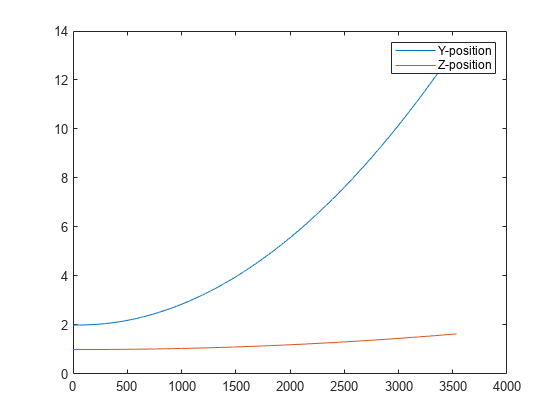
Plot the change in the Y and Z positions. With the specified thrust and roll angle, the multirotor should fly over and lose some altitude. A positive value for Z is expected as positive Z is down.
figure
plot(simOut.y(2,:));
hold on
plot(simOut.y(3,:));
legend('Y-position','Z-position')
hold off
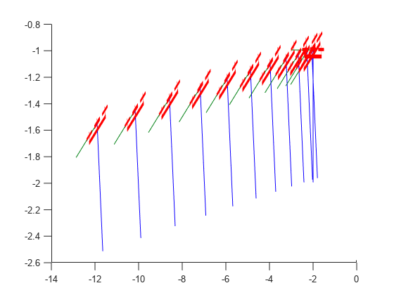
You can also plot the multirotor trajectory using plotTransforms. Create the translation and rotation vectors from the simulated state. Downsample (every 300th element) and transpose the simOut elements, and convert the Euler angles to quaternions. Specify the mesh as the multirotor.stl file and the positive Z-direction as "down". The displayed view shows the UAV translating in the Y-direction and losing altitude.
translations = simOut.y(1:3,1:300:end)'; % xyz position
rotations = eul2quat(simOut.y(7:9,1:300:end)'); % ZYX Euler
plotTransforms(translations,rotations,...
    'MeshFilePath','multirotor.stl','InertialZDirection',"down")
view([90.00 -0.60])
This example shows how to use the fixedwing guidance model to simulate the change in state of a UAV due to a command input.
Create the fixed-wing guidance model.
model = fixedwing;
Set the air speed of the vehicle by modifying the structure from the state function.
s = state(model);
s(4) = 5; % 5 m/s
Specify a control command, u, that maintains the air speed and gives a roll angle of pi/12.
u = control(model);
u.RollAngle = pi/12;
u.AirSpeed = 5;
Create a default environment without wind.
e = environment(model);
Compute the time derivative of the state given the current state, control command, and environment.
sdot = derivative(model,s,u,e);
Simulate the UAV state using ode45 integration. The y field outputs the fixed-wing UAV states based on this simulation.
simOut = ode45(@(~,x)derivative(model,x,u,e), [0 50], s);
size(simOut.y)
ans = 1×2

     8   904
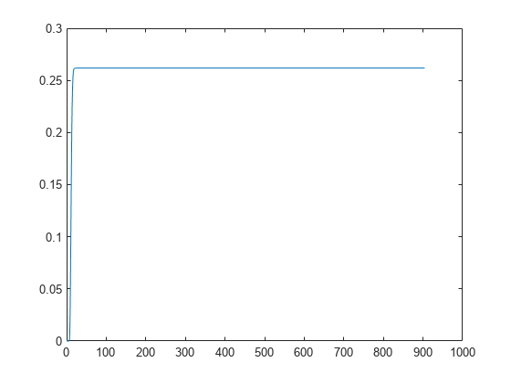
Plot the change in roll angle based on the simulation output. The roll angle is the 7th row of the simOut.y output.
plot(simOut.y(7,:))
You can also plot the fixed-wing trajectory using plotTransforms. Create the translation and rotation vectors from the simulated state. Downsample (every 30th element) and transpose the simOut elements, and convert the Euler angles to quaternions. Specify the mesh as the fixedwing.stl file and the positive Z-direction as "down". The displayed view shows the UAV making a constant turn based on the constant roll angle.
downsample = 1:30:size(simOut.y,2);
translations = simOut.y(1:3,downsample)'; % xyz-position
rotations = eul2quat([simOut.y(5,downsample)',simOut.y(6,downsample)',simOut.y(7,downsample)']); % ZYX Euler
plotTransforms(translations,rotations,...
    'MeshFilePath','fixedwing.stl','InertialZDirection',"down")
hold on
plot3(simOut.y(1,:),-simOut.y(2,:),simOut.y(3,:),'--b') % full path
xlim([-10.0 10.0])
ylim([-20.0 5.0])
zlim([-0.5 4.00])
view([-45 90])
hold off

Input Arguments
Output Arguments
Extended Capabilities
Version History
Introduced in R2018b