Simulate UAV Scenario Using Scenario Blocks
R2026bThis example shows how to use the UAV scenario blocks to simulate a scenario in Simulink®.
Create Scenario
Initialize your UAV scenario with meshes and uavPlatform objects for the UAV Scenario blocks to use.
% Initialize the scenario
scene = uavScenario(UpdateRate=100,ReferenceLocation=[0 0 0]);

%Create a ground for visualization
addMesh(scene,"polygon",{[-15 -15; 15 -15; 15 15; -15 15] [-0.5 0]},[0.3 0.3 0.3]);

% Add cylinder meshes to scan with lidar sensor
addMesh(scene,"cylinder",{[-5 5 2],[0 12]},[0 1 0]);
addMesh(scene,"cylinder",{[5 5 2],[0 12]},[0 1 0]);
addMesh(scene,"cylinder",{[5 -5 2],[0 12]},[0 1 0]);
Create one UAV platform to be controlled and another to be stationary.
% Platform/UAV initial position and orientation
initpos = [0 0 -5]; % NED Frame
initori = [0 0 0];

% Add two UAV Platform to the scenario and scale them for easier visualization
platform = uavPlatform("platformUAV",scene,ReferenceFrame="NED",...
    InitialPosition=initpos,InitialOrientation=eul2quat(initori));

updateMesh(platform,"quadrotor",{2},[0 0 0],eul2tform([0 0 pi]));

platform2 = uavPlatform("platformUAV2", scene, "ReferenceFrame", "NED", ...
    "InitialPosition", [0 7 -11], "InitialOrientation", eul2quat(initori));

updateMesh(platform2,"quadrotor", {2}, [0 0 0], eul2tform([0 0 pi]));
Create a uavSensor with a lidar sensor model using the uavLidarPointCloudGenerator and attach it to the first UAV platform. This sensor will be used in the Simulink simulation but the specifications of the lidar should be specified in the UAV Scenario Lidar block because they will not be loaded into the model.
LidarModel = uavLidarPointCloudGenerator();
uavSensor("Lidar",platform,LidarModel,"MountingLocation",[0,0,1],"MountingAngles",[0 0 180]);
Configure the Scenario
open_system("UAVScenarioModel.slx")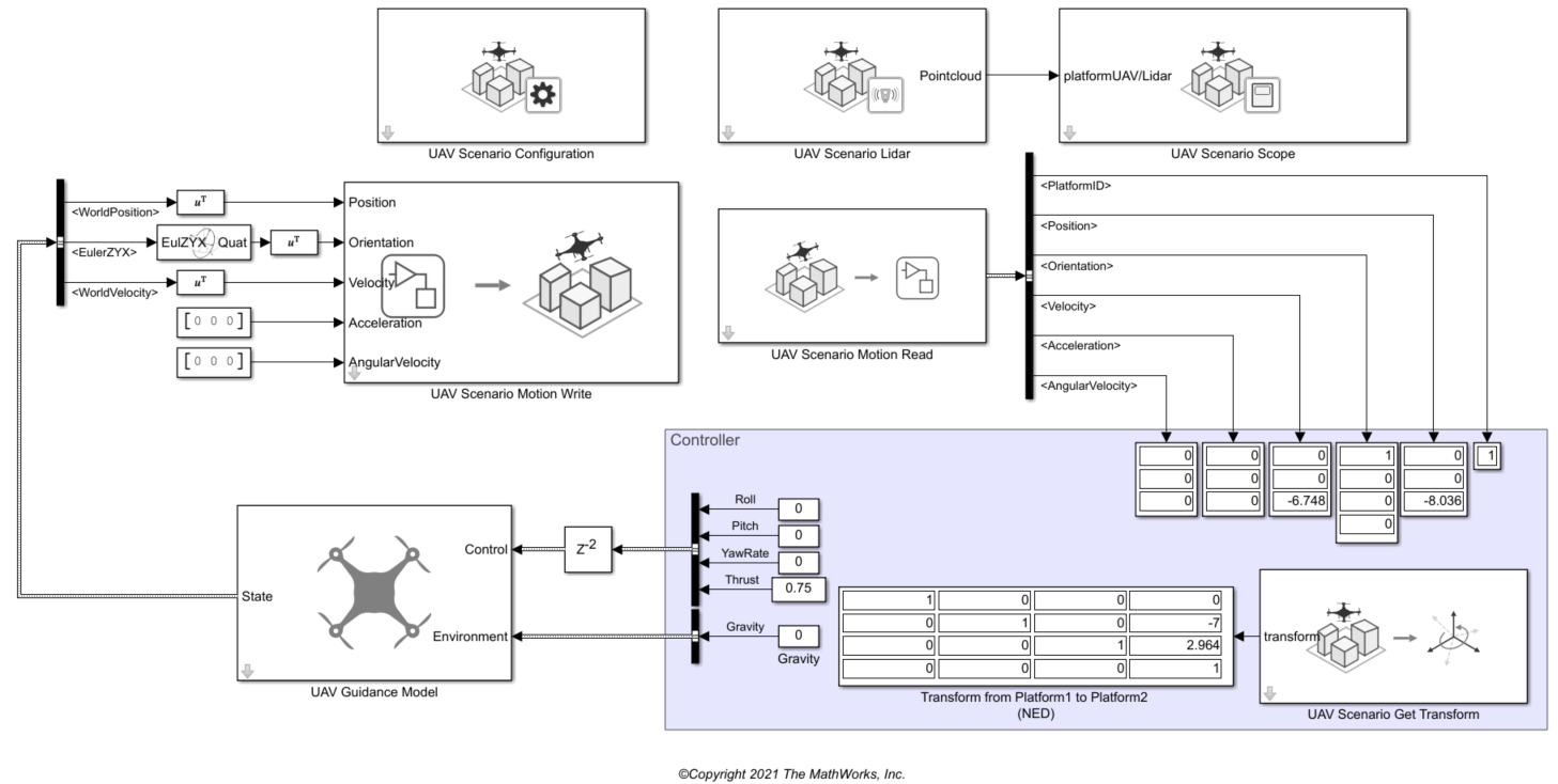
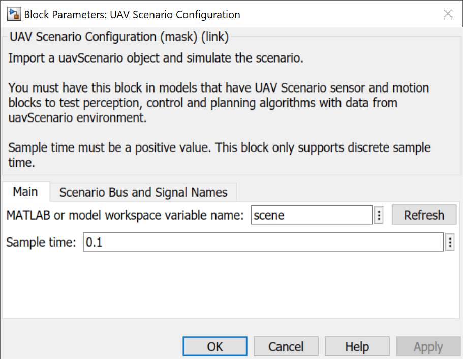
The UAV Scenario Configuration block is essential to simulating the UAV scenario in Simulink and must execute first. Place it in the model and set the MATLAB or model workspace variable name to the name of your scenario. Open this block and click Refresh whenever the scenario scene is changed in MATLAB to reflect those changes in Simulink. Change the sample time, and bus and signal names as necessary.
Write to Motion Bus
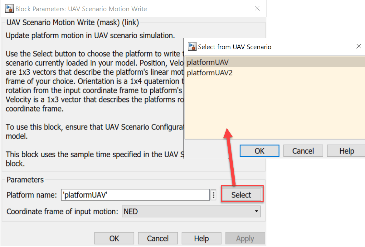
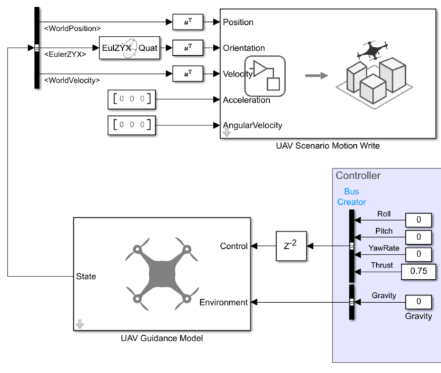
Use the UAV Scenario Motion Write block to update the Motion bus of the first platform UAV. This will update the position of the UAV in the UAV Scenario Scope block simulation. Open the block and click Select to choose the first platform UAV. This is the platform UAV that we will be updating with this block.
This example uses a multirotor guidance model with constant inputs as the plant to determine the next position to write to the motion bus. However, any kind of plant or controller can be used to update the motion bus of the platform if you can extract inputs to be used in the UAV Scenario Motion Write block.
Read from Motion Bus
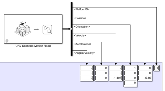
After writing to the motion bus with the UAV Scenario Motion Write block, the motion block can be read using the UAV Scenario Motion Read block. This data can be used in your controller it determine the inputs to your plant. This example does not use a controller so the outputs are read into Display blocks. Open the block and click Select to choose the same UAV as you selected in the UAV Scenario Motion Write block.
Get Transform
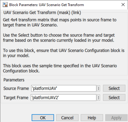
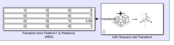
Use the UAV Scenario Get Transform block to get the transformation matrix between the two UAVs. Open the block and set the Source Frame to the first UAV and the Target Frame to the second UAV.
The transformation matrix in this example is displayed in a Display block, however the transformation data could have many applications in a controller.
View and Simulate Lidar
Use the UAV Scenario Lidar Block to use the lidar sensor created in the scenario. Open the block and specify the Sensor name by clicking the Select to choose the lidar sensor in the scene. The settings of the lidar can be edited by specifying the parameters in the block.
![UAV Scenario Lidar block parameters with Sensor name platformUAV/Lidar, Max range 120 m, and Azimuthal limits [-180, 180] degrees](../../examples/uav/SimulateUAVScenarioUsingScenarioBlocksExample_08.png)
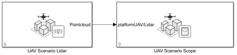
To visualize the lidar readings and the motion of the UAV, connect the UAV Scenario Lidar block to a UAV Scenario Scope block. To do so, you need to create a port by enabling the visualization toggle for the sensors you would like to connect. If you recently added a lidar sensor but do not see it in the table, try clicking Refresh in your UAV Configuration block and Refresh sensor table in this block.
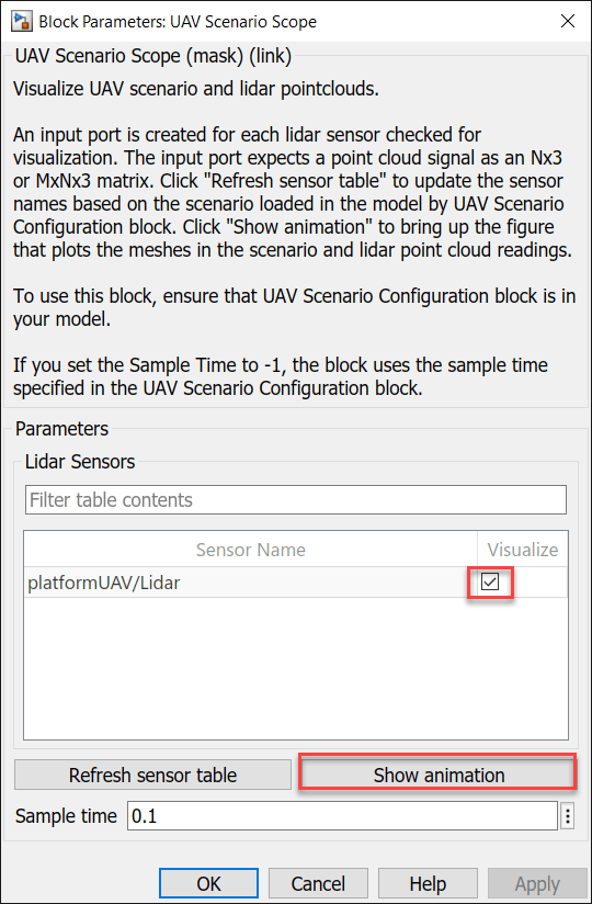
After enabling the visualization of the sensor, a port will appear on the UAV Scenario Scope block with the name of the platform and its sensor.
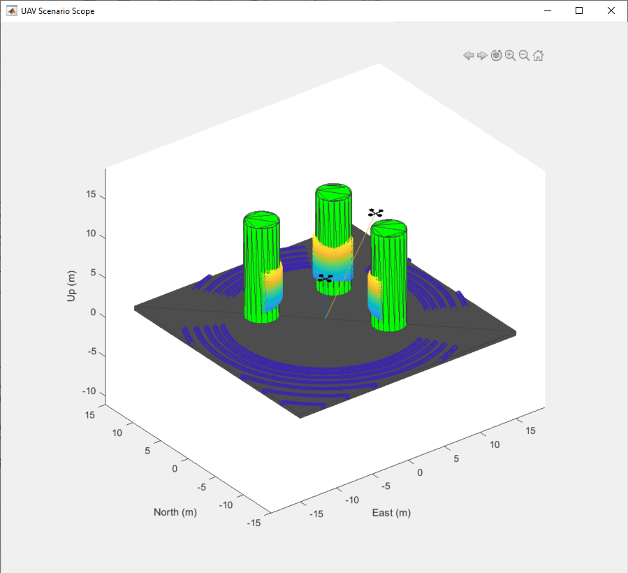
Click Show animation in the UAV Scenario Scope block to view the scenario, and run the model to see the animation.