Simulation 3D Terrain Sensor
Libraries:
Vehicle Dynamics Blockset /
Vehicle Scenarios /
Sim3D /
Sim3D Vehicle /
Components
Description
Note
Simulating models with the Simulation 3D Terrain Sensor block requires Simulink® 3D Animation™.
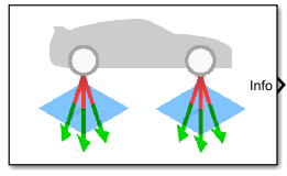
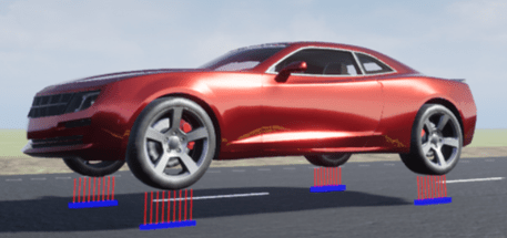
The Simulation 3D Terrain Sensor block implements a multipoint terrain sensor in Unreal Engine®. Use the block for contact modeling at high vehicle velocities over terrain changes, including speed bumps. The block implements ray tracing to detect the terrain below the tires. Use the block parameters to:
Sense the terrain under any simulation 3D vehicle actor in the scene, including actors created by the Simulation 3D Vehicle and Simulation 3D Motorcycle blocks.
Configure the ray origins, directions, and lengths to adjust the terrain sensor pattern for your scene and test scenario. Ray length specifies the range of the senor. Ray origins and directions follow the world coordinate system, where:
The X-axis points forward from the vehicle.
The Y-axis points to the right of the vehicle, as viewed when looking in the forward direction of the vehicle.
The Z-axis points up.
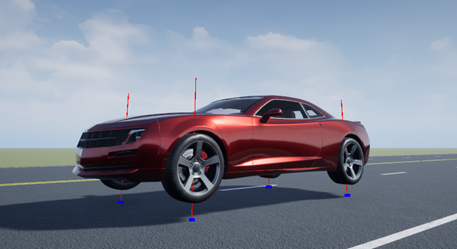
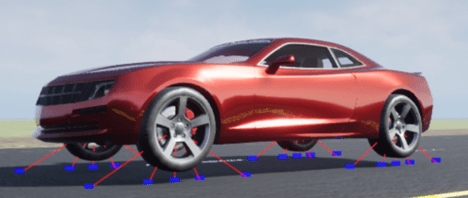
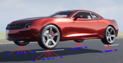
The block creates a terrain sensor pattern for each of the wheels on the vehicle actor. For specific patterns, this table provides the corresponding parameter settings.
| Pattern | Description | Parameter Settings |
|---|---|---|
|
|
|
|
|
|
|
|
|
|
|
|
Tip
Verify that the Simulation 3D Scene
Configuration block executes before the Simulation 3D Terrain
Sensor block. That way, the Unreal Engine 3D visualization environment prepares the data before the Simulation 3D
Terrain Sensor block receives it. To check the block execution order, right-click
the blocks and then click the Properties button ![]() . On the General tab, confirm these
Priority settings:
. On the General tab, confirm these
Priority settings:
Simulation 3D Scene Configuration —
0Simulation 3D Terrain Sensor —
1
For more information about execution order, see Control and Display Execution Order.
The Coordinate system parameter of the block specifies how the actor transformations are applied in the 3D environment. The output of the block also follows the specified coordinate system.
Examples

Constant Radius Reference Application
Simulate a full vehicle dynamics model undergoing a constant radius maneuver. Use for vehicle dynamics ride and handling analysis and chassis controls development, including the dynamic steering response.
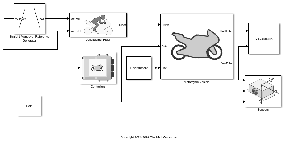
Longitudinal Motorcycle Braking Test Reference Application
Simulate an in-plane motorcycle model undergoing a braking test. Use for motorcycle dynamics ride and handling analysis and chassis controls development.