Simulation 3D Vehicle
Implement vehicle in 3D environment
Libraries:
Vehicle Dynamics Blockset /
Vehicle Scenarios /
Sim3D /
Sim3D Vehicle /
Components
Description
Note
Simulating models with the Simulation 3D Vehicle block requires Simulink® 3D Animation™.
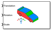
The Simulation 3D Vehicle block implements a vehicle with four wheels in the 3D simulation environment.
To use this block, ensure that the Simulation 3D Scene Configuration block
is in your model. If you set the Sample time parameter of this block to
-1, the block uses the sample time specified in the Simulation 3D
Scene Configuration block.
The block input uses the vehicle Z-down right-handed (RH) Cartesian coordinate system defined in SAE J6701. The coordinate system is inertial and initially aligned with the vehicle geometric center:
X-axis — Along vehicle longitudinal axis, points forward
Y-axis — Along vehicle lateral axis, points to the right
Z-axis — Points downward
Tip
Verify that the Simulation 3D Vehicle
block executes before the Simulation 3D Scene Configuration block. That way,
Simulation 3D Vehicle prepares the signal data before the Unreal Engine® 3D visualization environment receives it. To check the block execution order,
right-click the blocks and then click the Properties button ![]() . On the General tab, confirm these
Priority settings:
. On the General tab, confirm these
Priority settings:
Simulation 3D Scene Configuration —
0Simulation 3D Vehicle —
-1
For more information about execution order, see Control and Display Execution Order.
You can configure the Simulation 3D Vehicle block to import custom meshes and control vehicle lights.
Examples
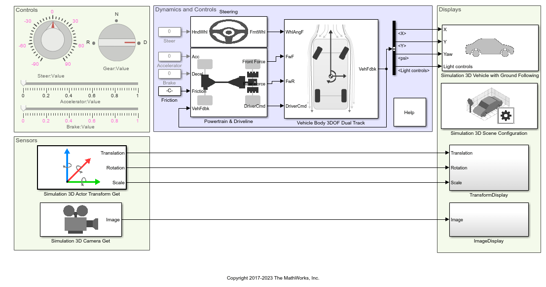
Scene Interrogation with Camera and Ray Tracing Reference Application
Interrogate a 3D Unreal Engine scene with a vehicle dynamics model by using a camera and ray tracing reference application project.
Ports
Input
Vehicle and wheel translation, in m. Array dimensions are
5-by-3.
Translation(1,1),Translation(1,2), andTranslation(1,3)— Vehicle translation along the inertial vehicle Z-down X-, Y-, and Z- axes, respectively.Translation(...,1),Translation(...,2), andTranslation(...,3)— Wheel translation relative to vehicle, along the vehicle Z-down X-, Y-, and Z- axes, respectively.
The signal contains translation information according to the axle and wheel locations.
| Translation | Array Element | Translation Axis |
|---|---|---|
Vehicle, Xv | Translation(1,1) | Inertial vehicle Z-down X-axis |
Vehicle, Yv | Translation(1,2) | Inertial vehicle Z-down Y-axis |
Vehicle, Zv | Translation(1,3) | Inertial vehicle Z-down Z-axis |
Front left wheel, XFL | Translation(2,1) | Vehicle Z-down X-axis |
Front left wheel, YFL | Translation(2,2) | Vehicle Z-down Y-axis |
Front left wheel, ZFL | Translation(2,3) | Vehicle Z-down Z-axis |
Front right wheel, XFR | Translation(3,1) | Vehicle Z-down X-axis |
Front right wheel, YFR | Translation(3,2) | Vehicle Z-down Y-axis |
Front right wheel, ZFR | Translation(3,3) | Vehicle Z-down Z-axis |
Rear left wheel, XRL | Translation(4,1) | Vehicle Z-down X-axis |
Rear left wheel, YRL | Translation(4,2) | Vehicle Z-down Y-axis |
Rear left wheel, ZRL | Translation(4,3) | Vehicle Z-down Z-axis |
Rear right wheel, XRR | Translation(5,1) | Vehicle Z-down X-axis |
Rear right wheel, YRR | Translation(5,2) | Vehicle Z-down Y-axis |
Rear right wheel, ZRR | Translation(5,3) | Vehicle Z-down Z-axis |
Vehicle and wheel rotation, in rad. Array dimensions are
5-by-3.
Rotation(1,1),Rotation(1,2), andRotation(1,3)— Vehicle rotation about the inertial vehicle Z-down X-, Y-, and Z- axes, respectively.Rotation(...,1),Rotation(...,2), andRotation(...,3)— Wheel rotation relative to vehicle, about the vehicle Z-down X-, Y-, and Z- axes, respectively.
The signal contains rotation information according to the axle and wheel locations.
| Rotation | Array Element | Rotation Axis |
|---|---|---|
Vehicle, Rollv | Rotation(1,1) | Inertial vehicle Z-down X-axis |
Vehicle, Pitchv | Rotation(1,2) | Inertial vehicle Z-down Y-axis |
Vehicle, Yawv | Rotation(1,3) | Inertial vehicle Z-down Z-axis |
Front left wheel, RollFL | Rotation(2,1) | Vehicle Z-down X-axis |
Front left wheel, PitchFL | Rotation(2,2) | Vehicle Z-down Y-axis |
Front left wheel, YawFL | Rotation(2,3) | Vehicle Z-down Z-axis |
Front right wheel, RollFR | Rotation(3,1) | Vehicle Z-down X-axis |
Front right wheel, PitchFR | Rotation(3,2) | Vehicle Z-down Y-axis |
Front right wheel, YawFR | Rotation(3,3) | Vehicle Z-down Z-axis |
Rear left wheel, RollRL | Rotation(4,1) | Vehicle Z-down X-axis |
Rear left wheel, PitchRL | Rotation(4,2) | Vehicle Z-down Y-axis |
Rear left wheel, YawRL | Rotation(4,3) | Vehicle Z-down Z-axis |
Rear right wheel, RollRR | Rotation(5,1) | Vehicle Z-down X-axis |
Rear right wheel, PitchRR | Rotation(5,2) | Vehicle Z-down Y-axis |
Rear right wheel, YawRR | Rotation(5,3) | Vehicle Z-down Z-axis |
Vehicle and wheel scale, dimensionless. Array dimensions are
5-by-3.
Scale(1,1),Scale(1,2), andScale(1,3)— Vehicle scale along the inertial vehicle Z-down X-, Y-, and Z- axes, respectively.Scale(...,1),Scale(...,2), andScale(...,3)— Wheel scale relative to vehicle, along vehicle Z-down X-, Y-, and Z- axes, respectively.
The signal contains scale information according to the axle and wheel locations.
| Scale | Array Element | Scale Axis |
|---|---|---|
Vehicle, Xvscale | Scale(1,1) | Vehicle Z-down X-axis |
Vehicle, Yvscale | Scale(1,2) | Vehicle Z-down Y-axis |
Vehicle, Zvscale | Scale(1,3) | Vehicle Z-down Z-axis |
Front left wheel, XFLscale | Scale(2,1) | Vehicle Z-down X-axis |
Front left wheel, YFLscale | Scale(2,2) | Vehicle Z-down Y-axis |
Front left wheel, ZFLscale | Scale(2,3) | Vehicle Z-down Z-axis |
Front right wheel, XFRscale | Scale(3,1) | Vehicle Z-down X-axis |
Front right wheel, YFRscale | Scale(3,2) | Vehicle Z-down Y-axis |
Front right wheel, ZFRscale | Scale(3,3) | Vehicle Z-down Z-axis |
Rear left wheel, XRLscale | Scale(4,1) | Vehicle Z-down X-axis |
Rear left wheel, YRLscale | Scale(4,2) | Vehicle Z-down Y-axis |
Rear left wheel, ZRLscale | Scale(4,3) | Vehicle Z-down Z-axis |
Rear right wheel, XRRscale | Scale(5,1) | Vehicle Z-down X-axis |
Rear right wheel, YRRscale | Scale(5,2) | Vehicle Z-down Y-axis |
Rear right wheel, ZRRscale | Scale(5,3) | Vehicle Z-down Z-axis |
Light controls input signal, specified as a 1-by-6 Boolean vector. Each element of the vector turns a specific vehicle light on or off, as indicated in this table. A value of 1 turns the light on; a value of 0 turns the light off.
| Vector Element | Vehicle Light |
|---|---|
(1,1) | Headlight high beam |
(1,2) | Headlight low beam |
(1,3) | Brake |
(1,4) | Reverse |
(1,5) | Left signal |
(1,6) | Right signal |
Dependencies
To create this port, on the Light Controls tab, select Enable light controls.
Data Types: Boolean
Parameters
Vehicle Parameters
Specify the vehicle type. This table provides links to the vehicle dimensions.
| Vehicle type Setting | Vehicle Dimensions |
|---|---|
Muscle car | |
Sedan | |
Sport utility vehicle | |
Small pickup truck | |
Hatchback | |
Box truck | |
Formula Student Vehicle |
Dependencies
Selecting Custom enables parameters that allow you to import a
custom mesh for your vehicle.
Programmatic Use
To set the block parameter value
programmatically, use the set_param function.
To get the block parameter value
programmatically, use the get_param function.
| Parameter: | PassVehMesh |
| Values: | Muscle car (default) | Sedan | Sport utility vehicle | Small pickup truck | Hatchback | Box Truck | Formula student vehicle | Custom |
| Data Types: | character vector |
Path to custom mesh.
To create a custom vehicle mesh, see Prepare Custom Vehicle Mesh for the Unreal Editor.
Example: /MathWorksSimulation/Vehicles/Muscle/Meshes/SK_Sedan.SK_Sedan
Dependencies
To enable this parameter, set Type to
Custom.
Programmatic Use
To set the block parameter value
programmatically, use the set_param function.
To get the block parameter value
programmatically, use the get_param function.
| Parameter: | MeshPath |
| Values: | /MathWorksSimulation/Vehicles/Muscle/Meshes/SK_MuscleCar.SK_MuscleCar (default) | valid path |
| Data Types: | character vector |
Select the color of the vehicle.
Programmatic Use
To set the block parameter value
programmatically, use the set_param function.
To get the block parameter value
programmatically, use the get_param function.
| Parameter: | VehColor |
| Values: | Red (default) | Orange | Yellow | Green | Blue | Black | White | Silver | Dazzle camouflage |
| Data Types: | character vector |
Name of vehicle. By default, when you use the block in your model, the block sets
the Name parameter to
SimulinkVehicle. The value of
XX
Programmatic Use
To set the block parameter value
programmatically, use the set_param function.
To get the block parameter value
programmatically, use the get_param function.
| Parameter: | ActorName |
| Values: | SimulinkVehicle1 (default) | character vector |
| Data Types: | double |
Sample time, Ts. The graphics frame rate is the inverse of the sample time.
Programmatic Use
To set the block parameter value
programmatically, use the set_param function.
To get the block parameter value
programmatically, use the get_param function.
| Parameter: | SampleTime |
| Values: | -1 (default) | scalar |
| Data Types: | double |
Light Controls
Select whether to control the vehicle headlights. Use the enabled parameters to set the light parameters, including headlight intensity.
Dependencies
Selecting this parameter:
Creates the input port
Light controls.Enables these light parameters.
Lights Light Parameters Headlights Headlight color
High beam intensity
Low beam intensity
High beam cone half angle
Low beam cone half angle
Left headlight beam orientation
Right headlight beam orientation
Brake lights Brake light intensity
Reverse lights Reverse light intensity
Turn signal lights Turn signal light intensity
Period
Pulse width
Programmatic Use
To set the block parameter
value programmatically, use the set_param
function.
To get the block parameter
value programmatically, use the get_param function.
| Parameter: | VehLightsControl |
| Values: | Off (default) | On |
| Data Types: | character vector |
Headlights
Headlight color, specified as a normalized 1-by-3 vector of RGB triplet values.
Dependencies
To enable this parameter, select Enable light controls.
Programmatic Use
To set the block parameter
value programmatically, use the set_param
function.
To get the block parameter
value programmatically, use the get_param function.
| Parameter: | HeadlightColor |
| Values: | [1,1,1] (default) | vector |
| Data Types: | double |
High beam intensity, in cd.
Dependencies
To enable this parameter, select Enable light controls.
Programmatic Use
To set the block parameter
value programmatically, use the set_param
function.
To get the block parameter
value programmatically, use the get_param function.
| Parameter: | HighBeamIntensity |
| Values: | 100000 (default) | scalar |
| Data Types: | double |
Low beam intensity, in cd.
Dependencies
To enable this parameter, select Enable light controls.
Programmatic Use
To set the block parameter
value programmatically, use the set_param
function.
To get the block parameter
value programmatically, use the get_param function.
| Parameter: | LowBeamIntensity |
| Values: | 60000 (default) | scalar |
| Data Types: | double |
High beam cone half angle, in rad.
Dependencies
To enable this parameter, select Enable light controls.
Programmatic Use
To set the block parameter
value programmatically, use the set_param
function.
To get the block parameter
value programmatically, use the get_param function.
| Parameter: | HighBeamConeAngle |
| Values: | 1.22 (default) | scalar |
| Data Types: | double |
Low beam cone half angle, in rad.
Dependencies
To enable this parameter, select Enable light controls.
Programmatic Use
To set the block parameter
value programmatically, use the set_param
function.
To get the block parameter
value programmatically, use the get_param function.
| Parameter: | LowBeamConeAngle |
| Values: | 1.22 (default) | scalar |
| Data Types: | double |
Pitch and yaw orientation of the left headlight beam orientation in the
Z-down coordinate system, specified as a 1-by-2 vector,
in rad. The first element of the vector, [1,1], is the pitch
angle. The second element of the vector, [1,2], is the yaw
angle.
Dependencies
To enable this parameter, select Enable light controls.
Programmatic Use
To set the block parameter
value programmatically, use the set_param
function.
To get the block parameter
value programmatically, use the get_param function.
| Parameter: | LeftHeadlightOrientation |
| Values: | [0,0] (default) | vector |
| Data Types: | double |
Pitch and yaw orientation of the right headlight beam orientation in the
Z-down coordinate system, specified as a 1-by-2 vector,
in rad. The first element of the vector, [1,1], is the pitch
angle. The second element of the vector, [1,2], is the yaw
angle.
Dependencies
To enable this parameter, select Enable light controls.
Programmatic Use
To set the block parameter
value programmatically, use the set_param
function.
To get the block parameter
value programmatically, use the get_param function.
| Parameter: | RightHeadlightOrientation |
| Values: | [0,0] (default) | vector |
| Data Types: | double |
Brake Lights
Brake light intensity, in cd/m^2.
Dependencies
To enable this parameter, select Enable light controls.
Programmatic Use
To set the block parameter
value programmatically, use the set_param
function.
To get the block parameter
value programmatically, use the get_param function.
| Parameter: | BrakelightIntensity |
| Values: | 500 (default) | scalar |
| Data Types: | double |
Reverse Lights
Reverse light intensity, in cd/m^2.
Dependencies
To enable this parameter, select Enable light controls.
Programmatic Use
To set the block parameter
value programmatically, use the set_param
function.
To get the block parameter
value programmatically, use the get_param function.
| Parameter: | ReverselightIntensity |
| Values: | 500 (default) | scalar |
| Data Types: | double |
Turn Signal Lights
Turn signal light intensity, in cd/m^2.
Dependencies
To enable this parameter, select Enable light controls.
Programmatic Use
To set the block parameter
value programmatically, use the set_param
function.
To get the block parameter
value programmatically, use the get_param function.
| Parameter: | SignallightIntensity |
| Values: | 500 (default) | scalar |
| Data Types: | double |
Turn signal light period, in s.
Dependencies
To enable this parameter, select Enable light controls.
Programmatic Use
To set the block parameter
value programmatically, use the set_param
function.
To get the block parameter
value programmatically, use the get_param function.
| Parameter: | SignallightPeriod |
| Values: | 1 (default) | scalar |
| Data Types: | double |
Turn signal light pulse width, specified as a percent of the period.
Dependencies
To enable this parameter, select Enable light controls.
Programmatic Use
To set the block parameter
value programmatically, use the set_param
function.
To get the block parameter
value programmatically, use the get_param function.
| Parameter: | SignalPulseWidth |
| Values: | 50 (default) | scalar |
| Data Types: | double |
Initial Values
Initial vehicle and wheel translation, in m. Array dimensions are
5-by-3.
Translation(1,1),Translation(1,2), andTranslation(1,3)— Initial vehicle translation along the inertial vehicle Z-down coordinate system X-, Y-, and Z- axes, respectively.Translation(...,1),Translation(...,2), andTranslation(...,3)— Initial wheel translation relative to vehicle, along the vehicle Z-down X-, Y-, and Z- axes, respectively.
The parameter contains translation information according to the axle and wheel locations.
| Translation | Array Element | Translation Axis |
|---|---|---|
Vehicle, Xv | Translation(1,1) | Inertial vehicle Z-down X-axis |
Vehicle, Yv | Translation(1,2) | Inertial vehicle Z-down Y-axis |
Vehicle, Zv | Translation(1,3) | Inertial vehicle Z-down Z-axis |
Front left wheel, XFL | Translation(2,1) | Vehicle Z-down X-axis |
Front left wheel, YFL | Translation(2,2) | Vehicle Z-down Y-axis |
Front left wheel, ZFL | Translation(2,3) | Vehicle Z-down Z-axis |
Front right wheel, XFR | Translation(3,1) | Vehicle Z-down X-axis |
Front right wheel, YFR | Translation(3,2) | Vehicle Z-down Y-axis |
Front right wheel, ZFR | Translation(3,3) | Vehicle Z-down Z-axis |
Rear left wheel, XRL | Translation(4,1) | Vehicle Z-down X-axis |
Rear left wheel, YRL | Translation(4,2) | Vehicle Z-down Y-axis |
Rear left wheel, ZRL | Translation(4,3) | Vehicle Z-down Z-axis |
Rear right wheel, XRR | Translation(5,1) | Vehicle Z-down X-axis |
Rear right wheel, YRR | Translation(5,2) | Vehicle Z-down Y-axis |
Rear right wheel, ZRR | Translation(5,3) | Vehicle Z-down Z-axis |
Programmatic Use
To set the block parameter value
programmatically, use the set_param function.
To get the block parameter value
programmatically, use the get_param function.
| Parameter: | Translation |
| Values: | zeros(5,3) (default) | 5-by-3 array |
| Data Types: | double |
Initial vehicle and wheel rotation, about the vehicle Z-down X-, Y-, and Z- axes.
Array dimensions are 5-by-3.
Rotation(1,1),Rotation(1,2), andRotation(1,3)— Initial vehicle rotation about the inertial vehicle Z-down coordinate system X-, Y-, and Z- axes, respectively.Rotation(...,1),Rotation(...,2), andRotation(...,3)— Initial wheel rotation relative to vehicle, about the vehicle Z-down X-, Y-, and Z- axes, respectively.
The parameter contains rotation information according to the axle and wheel locations.
| Rotation | Array Element | Rotation Axis |
|---|---|---|
Vehicle, Rollv | Rotation(1,1) | Inertial vehicle Z-down X-axis |
Vehicle, Pitchv | Rotation(1,2) | Inertial vehicle Z-down Y-axis |
Vehicle, Yawv | Rotation(1,3) | Inertial vehicle Z-down Z-axis |
Front left wheel, RollFL | Rotation(2,1) | Vehicle Z-down X-axis |
Front left wheel, PitchFL | Rotation(2,2) | Vehicle Z-down Y-axis |
Front left wheel, YawFL | Rotation(2,3) | Vehicle Z-down Z-axis |
Front right wheel, RollFR | Rotation(3,1) | Vehicle Z-down X-axis |
Front right wheel, PitchFR | Rotation(3,2) | Vehicle Z-down Y-axis |
Front right wheel, YawFR | Rotation(3,3) | Vehicle Z-down Z-axis |
Rear left wheel, RollRL | Rotation(4,1) | Vehicle Z-down X-axis |
Rear left wheel, PitchRL | Rotation(4,2) | Vehicle Z-down Y-axis |
Rear left wheel, YawRL | Rotation(4,3) | Vehicle Z-down Z-axis |
Rear right wheel, RollRR | Rotation(5,1) | Vehicle Z-down X-axis |
Rear right wheel, PitchRR | Rotation(5,2) | Vehicle Z-down Y-axis |
Rear right wheel, YawRR | Rotation(5,3) | Vehicle Z-down Z-axis |
Programmatic Use
To set the block parameter value
programmatically, use the set_param function.
To get the block parameter value
programmatically, use the get_param function.
| Parameter: | Rotation |
| Values: | zeros(5,3) (default) | 5-by-3 array |
| Data Types: | double |
Initial vehicle and wheel scale, dimensionless. Array dimensions are
5-by-3.
Scale(1,1),Scale(1,2), andScale(1,3)— Initial vehicle scale along the inertial vehicle Z-down X-, Y-, and Z- axes, respectively.Scale(...,1),Scale(...,2), andScale(...,3)— Initial wheel scale relative to vehicle, along vehicle Z-down X-, Y-, and Z- axes, respectively.
The parameter contains scale information according to the axle and wheel locations.
| Scale | Array Element | Scale Axis |
|---|---|---|
Vehicle, Xvscale | Scale(1,1) | Vehicle Z-down X-axis |
Vehicle, Yvscale | Scale(1,2) | Vehicle Z-down Y-axis |
Vehicle, Zvscale | Scale(1,3) | Vehicle Z-down Z-axis |
Front left wheel, XFLscale | Scale(2,1) | Vehicle Z-down X-axis |
Front left wheel, YFLscale | Scale(2,2) | Vehicle Z-down Y-axis |
Front left wheel, ZFLscale | Scale(2,3) | Vehicle Z-down Z-axis |
Front right wheel, XFRscale | Scale(3,1) | Vehicle Z-down X-axis |
Front right wheel, YFRscale | Scale(3,2) | Vehicle Z-down Y-axis |
Front right wheel, ZFRscale | Scale(3,3) | Vehicle Z-down Z-axis |
Rear left wheel, XRLscale | Scale(4,1) | Vehicle Z-down X-axis |
Rear left wheel, YRLscale | Scale(4,2) | Vehicle Z-down Y-axis |
Rear left wheel, ZRLscale | Scale(4,3) | Vehicle Z-down Z-axis |
Rear right wheel, XRRscale | Scale(5,1) | Vehicle Z-down X-axis |
Rear right wheel, YRRscale | Scale(5,2) | Vehicle Z-down Y-axis |
Rear right wheel, ZRRscale | Scale(5,3) | Vehicle Z-down Z-axis |
Programmatic Use
To set the block parameter value
programmatically, use the set_param function.
To get the block parameter value
programmatically, use the get_param function.
| Parameter: | Scale |
| Values: | ones(5,3) (default) | 5-by-3 array |
| Data Types: | double |
More About
To import custom meshes for defining custom vehicles, follow these steps:
Install the Vehicle Dynamics Blockset™ Interface for Unreal Engine Projects support package. See Customize 3D Scenes for Vehicle Dynamics Simulations.
On the block Parameters tab, set Type to
Custom.In the Path to custom mesh field, enter the path to the vehicle mesh in the Unreal Engine project. For example, enter
/MathWorksSimulation/Vehicles/Muscle/Meshes/SK_MuscleCar.SK_MuscleCar.To create a custom vehicle mesh, see Prepare Custom Vehicle Mesh for the Unreal Editor.
Use the vehicle dimensions in the custom mesh to enter the dimensions in the corresponding block parameter fields.
To control the lights of vehicles in a scene, follow these steps:
Install the Vehicle Dynamics Blockset Interface for Unreal Engine Projects support package. See Customize 3D Scenes for Vehicle Dynamics Simulations.
On the block Light Controls tab, select Enable light controls.
Use the enabled parameters to specify the vehicle lights for:
Headlights
Brake lights
Reverse lights
Turn signal lights
Connect Boolean light control signals to the
Signal lightsinput port.
References
[1] Vehicle Dynamics Standards Committee. Vehicle Dynamics Terminology. SAE J670. Warrendale, PA: Society of Automotive Engineers, 2008.
[2] Technical Committee. Road vehicles — Vehicle dynamics and road-holding ability — Vocabulary. ISO 8855:2011. Geneva, Switzerland: International Organization for Standardization, 2011.
Version History
Introduced in R2019bStarting in R2024b, you can specify Color, VehColor as
Dazzle Camouflage for the Simulation 3D Vehicle
block.
Simulating models with the Simulation 3D Vehicle block requires Simulink 3D Animation.
MATLAB Command
You clicked a link that corresponds to this MATLAB command:
Run the command by entering it in the MATLAB Command Window. Web browsers do not support MATLAB commands.
选择网站
选择网站以获取翻译的可用内容,以及查看当地活动和优惠。根据您的位置,我们建议您选择:。
您也可以从以下列表中选择网站:
如何获得最佳网站性能
选择中国网站(中文或英文)以获得最佳网站性能。其他 MathWorks 国家/地区网站并未针对您所在位置的访问进行优化。
美洲
- América Latina (Español)
- Canada (English)
- United States (English)
欧洲
- Belgium (English)
- Denmark (English)
- Deutschland (Deutsch)
- España (Español)
- Finland (English)
- France (Français)
- Ireland (English)
- Italia (Italiano)
- Luxembourg (English)
- Netherlands (English)
- Norway (English)
- Österreich (Deutsch)
- Portugal (English)
- Sweden (English)
- Switzerland
- United Kingdom (English)