Double-Lane Change Maneuver
This reference application represents a full vehicle dynamics model undergoing a double-lane change maneuver according to standard ISO 3888-1[4] or standard ISO 3888-2[5]. You can create your own versions, establishing a framework to test that your vehicle meets the design requirements under normal and extreme driving conditions. Use the reference application to analyze vehicle ride and handling and develop chassis controls. To perform vehicle studies, including yaw stability and lateral acceleration limits, use this reference application.
ISO 3888-1 defines the double-lane change maneuver. In the test, the driver:
Accelerates until the vehicle hits a target velocity
Holds the accelerator command
Turns the steering wheel to follow path into the left lane
Turns the steering wheel to follow path back into the right lane
ISO 3888-2 defines the double-lane change maneuver to test the obstacle avoidance performance of a vehicle. In the test, the driver:
Accelerates until vehicle hits a target velocity
Releases the accelerator pedal
Turns the steering wheel to follow path into the left lane
Turns the steering wheel to follow path back into the right lane
Typically, cones mark the lane boundaries. If the vehicle and driver can negotiate the maneuver without hitting a cone, the vehicle passes the test.
To test advanced driver assistance systems (ADAS) and automated driving (AD) perception, planning, and control software, you can run the maneuver in a 3D environment. The number of cones and spacing differences between the ISO 3888-1 and ISO 3888-2 tests are automatically reflected when running the maneuvers in a 3D environment. For the 3D visualization engine platform requirements and hardware recommendations, see Unreal Engine Simulation Environment Requirements and Limitations.
To create and open a working copy of the double-lane change reference application project, enter
This table summarizes the blocks and subsystems in the reference application. Some subsystems contain variants.
| Reference Application Element | Description | Variants |
|---|---|---|
Generates lane signals for the visualization subsystem and trajectory signals | ||
Implements the driver model that the reference application uses to generate acceleration, braking, gear, and steering commands. By default, Driver Commands subsystem variant is the Predictive Driver block. | ✓ | |
Implements wind and ground forces | ✓ | |
Implements controllers for engine control units (ECUs), transmissions, anti-lock braking systems (ABS), and active differentials. | ✓ | |
Implements the:
| ✓ | |
Provides the vehicle trajectory, driver response, and 3D visualization. Note Simulating models in the 3D visualization environment requires Simulink® 3D Animation™. | ✓ |
To override the default variant, on the Modeling tab, in the Design section, click the drop-down. In the General section, select Variant Manager. In the Variant Manager, navigate to the variant that you want to use. Right-click and select Override using this Choice.
Lane Change Reference Generator
Use the Lane Change Reference Generator block to select the lane change maneuver and generate:
Lane signals for the Visualization subsystem — The left and right lane boundaries are a function of the Vehicle width parameter.
Velocity and lateral reference signals for the Predictive Driver block — Use the Lateral reference position breakpoints and Lateral reference data parameters to specify the lateral reference trajectory as a function of the longitudinal distance.
By default, the Lane Change Reference Generator block is set with these parameters for the lane change maneuver ISO 3888-2.
| Parameter | Setting |
|---|---|
| Lane change type, changeType | Obstacle avoidance (ISO
3888-2) |
| Inertial Longitudinal position of gate entrance, XGate [m] | 175 |
| Longitudinal entrance velocity setpoint, xdot_r | 35 |
| Longitudinal entrance velocity setpoint units, xdocUnit[] | mph |
| Lateral reference position breakpoints, latRefpb [m] | DLCXrefStanley2 |
| Lateral reference data, latRef [m] | DLCYrefStanley2 |
For the lane change maneuver ISO 3888-1, set the Lane Change Reference Generator block to these parameters:
| Parameter | Setting |
|---|---|
| Lane change type, changeType | Double lane change (ISO
3888-1) |
| Inertial Longitudinal position of gate entrance, XGate [m] | 230 |
| Longitudinal entrance velocity setpoint, xdot_r | 80 |
| Longitudinal entrance velocity setpoint units, xdocUnit[] | km/hr |
| Lateral reference position breakpoints, latRefpb [m] | DLCXrefStanley1 |
| Lateral reference data, latRef [m] | DLCYrefStanley1 |
Set Stop Time to 30.
Alternatively, use these MATLAB commands to programmatically set the block parameters and the stop time.
mdl = 'DLCReferenceApplication';
blockPath = [mdl '/Lane Change Reference Generator'];
set_param(blockPath,'changeType','Double lane change (ISO 3888-1)',...
    'XGate','230',...
    'xdot_r','80',...
    'xdotUnit','km/hr',...
    'latRefbp',...
    'DLCXrefStanley1',...
    'latRef','DLCYrefStanley1')
set_param(mdl,'StopTime','30')
To start simulations from a non-zero steady-state velocities, use the Steady-state initial conditions and Steady-State Solver tab parameters. For an example, see Start Double-Lane Change Maneuver at Target Velocity.
Driver Commands
The Driver Commands block implements the driver model that the reference application uses to generate acceleration, braking, gear, and steering commands. By default, if you select the Reference Generator block parameter Use maneuver-specific driver, initial position, and scene, the reference application selects the driver for the maneuver that you specified.
Vehicle Command Mode Setting | Implementation |
|---|---|
| Longitudinal Driver block — Longitudinal speed-tracking controller. Based on reference and feedback velocities, the block generates normalized acceleration and braking commands that can vary from 0 through 1. Use the block to model the dynamic response of a driver or to generate the commands necessary to track a longitudinal drive cycle. |
| Predictive Driver block — Controller that generates normalized steering, acceleration, and braking commands to track longitudinal velocity and a lateral reference displacement. The normalized commands can vary between -1 to 1. The controller uses a single-track (bicycle) model for optimal single-point preview control. |
| Predictive Driver block — Controller that generates normalized steering, acceleration, and braking commands to track longitudinal velocity and a lateral reference displacement. The normalized commands can vary between -1 to 1.
|
| Implements an open-loop system so that you can configure the reference application for constant or signal-based steering, acceleration, braking, and gear command input. |
Environment
The Environment subsystem generates the wind and ground forces. The reference application has these environment variants.
| Environment | Variant | Description |
|---|---|---|
Ground Feedback |
| Uses Simulation 3D Terrain Sensor block to implement a multipoint terrain sensor in 3D environment |
| Implements a constant friction value |
Controllers
The Controllers subsystem generates engine torque, transmission gear, brake pressure, and differential pressure commands.
ECU
The ECU controller generates the engine torque command. The controller prevents
over-revving the engine by limiting the engine torque command to the value specified by
model workspace variable EngRevLim. By default, the value is 7000
rpm. If the differential torque command exceeds the limited engine torque command, the
ECU sets the engine torque command to the commanded differential torque.
Transmission Control
The Transmission Controller subsystem generates the transmission gear command. The controller includes these variants.
| Variant | Description |
|---|---|
| Open loop transmission control. The controller sets the gear command to the gear request. |
| Implements a transmission control module (TCM) that uses Stateflow® logic to generate the gear command based on the vehicle acceleration, brake command, wheel speed, engine speed, and gear request. |
| Implements a paddle controller that uses the vehicle acceleration and engine speed to generate the gear command. |
| Implements a transmission control module (TCM) that uses Stateflow logic to generate the gear command based on the vehicle acceleration, wheel speed, and engine speed. |
Brake Pressure Control
The Brake Controller subsystem implements a Brake Pressure Control subsystem to generate the brake pressure command. The Brake Pressure Control subsystem has these variants.
| Variant | Description |
|---|---|
| Implements an anti-lock braking system (ABS) feedback controller that switches between two states to regulate wheel slip. The bang-bang control minimizes the error between the actual slip and desired slip. For the desired slip, the controller uses the slip value at which the mu-slip curve reaches a peak value. This desired slip value is optimal for minimum braking distance. |
| Open loop brake control. The controller sets the brake pressure command to a reference brake pressure based on the brake command. |
| Five-state ABS control when you simulate the maneuver.1,2,3 The five-state ABS controller uses logic-switching based on wheel deceleration and vehicle acceleration to control the braking pressure at each wheel. Consider using five-state ABS control to prevent wheel lock-up, decrease braking distance, or maintain yaw stability during the maneuver. The default ABS parameters are set to work on roads that have a constant friction coefficient scaling factor of 0.6. |
Active Differential Control
The Active Differential Control subsystem generates the differential pressure command. To calculate the command, the subsystem has these variants.
| Variant | Description |
|---|---|
| Implements a controller that generates the differential pressure command based on the:
|
| Does not implement a controller. Sets the differential pressure command to 0. |
Passenger Vehicle
The Passenger Vehicle subsystem has an engine, controllers, and a vehicle body with four wheels. Specifically, the vehicle contains these subsystems.
| Body, Suspension, Wheels Subsystem | Variant | Description |
|---|---|---|
PassVeh7DOF |
| Vehicle with four wheels:
Subsystem has variants for the tires, including:
|
PassVeh14DOF |
| Vehicle with four wheels.
Subsystem has variants for the suspension, including:
Subsystem has variants for the tires, including:
|
| Engine Subsystem | Variant | Description |
|---|---|---|
Mapped Engine |
| Mapped spark-ignition (SI) engine |
Steering, Transmission, Driveline, and Brakes Subsystem | Variant | Description | |
|---|---|---|---|
Driveline Ideal Fixed Gear | Driveline model | All Wheel Drive | Configure the driveline for all-wheel, front-wheel, rear-wheel, or rear-wheel active differential drive and specify the type of torque coupling. |
| |||
| |||
| |||
Transmission |
| Implements an ideal fixed gear transmission. | |
Brake Hydraulics | NA | Implements the heuristic response of a hydraulic system when the controller applies a brake command to a cylinder. Includes front and rear wheel bias coefficients. The subsystem converts the applied pressure to a cylinder spool position. To generate the brake pressure, the spool applies a flow downstream to the cylinders. | |
Visualization
When you run the simulation, the Visualization subsystem provides driver, vehicle, and response information. The reference application logs vehicle signals during the maneuver, including steering, vehicle and engine speed, and lateral acceleration. You can use the Simulation Data Inspector to import the logged signals and examine the data.

| Element | Description |
|---|---|
Driver Commands | Driver commands:
|
Vehicle Response | Vehicle response:
|
Lane Change Scope block | Lateral vehicle displacement versus time:
|
Steer, Velocity, Lat Accel Scope block |
|
Vehicle XY Plotter | Vehicle longitudinal versus lateral distance |
ISO 15037-1:2006 block | Display ISO standard measurement signals in the Simulation Data Inspector, including steering wheel angle and torque, longitudinal and lateral velocity, and sideslip angle |
3D Visualization
Optionally, you can enable or disable the 3D visualization environment. For the 3D visualization engine platform requirements and hardware recommendations, see Unreal Engine Simulation Environment Requirements and Limitations. After you open the reference application, in the Visualization subsystem, open the 3D Engine block.
Note
Simulating models in the 3D visualization environment requires Simulink 3D Animation.
Set these parameters.
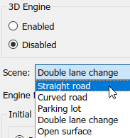
3D Engine to Enabled.
Scene to one of the scenes, for example
Straight
                    road
.
To position the vehicle in the scene:
Select the position initialization method:
Recommended for scene — Set the initial vehicle position to values recommended for the scene
User-specified — Set your own initial vehicle position
Click Update the model workspaces with the initial values to overwrite the initial vehicle position in the model workspaces with the applied values.
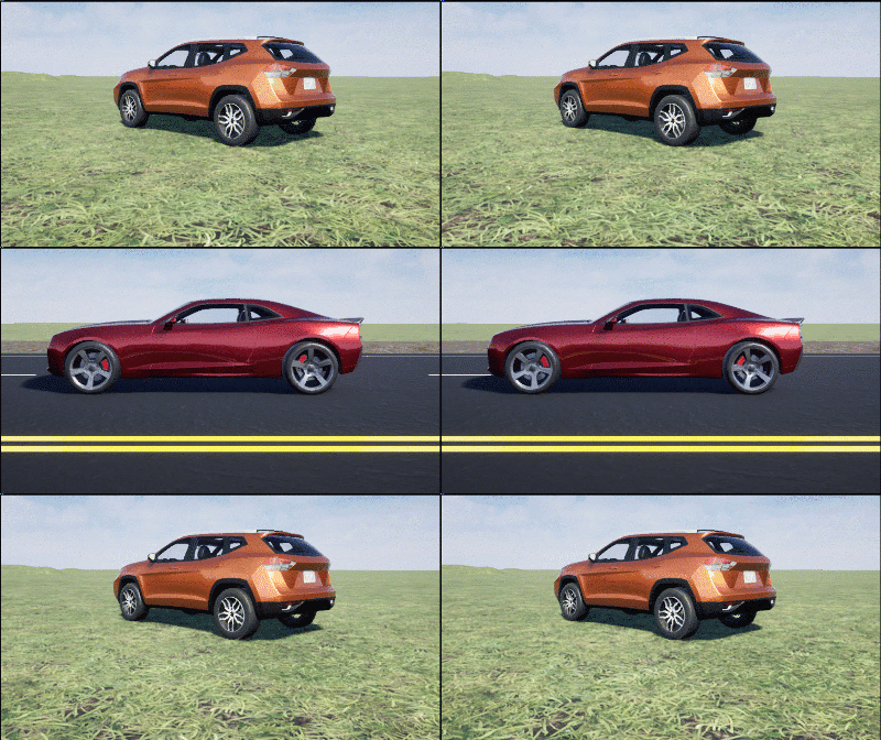
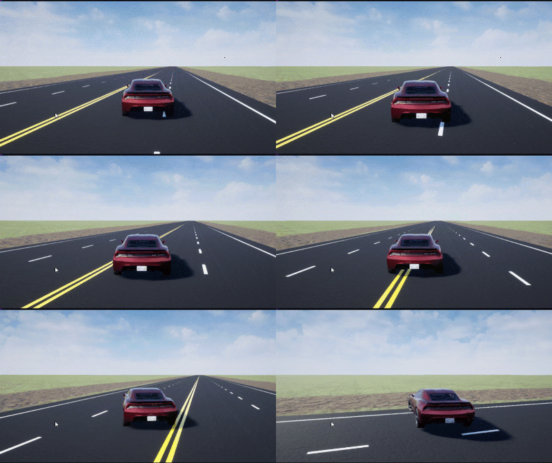
When you run the simulation, view the vehicle response in the Simulation 3D Viewer.
Note
To open and close the Simulation 3D Viewer, use the Simulink Run and Stop buttons. If you manually close the Simulation 3D Viewer, Simulink stops the simulation with an error.
When you enable the 3D visualization environment, you cannot step the simulation back.
To smoothly change the camera views, use these keyboard shortcuts.
| Keyboard Shortcut | Camera View | |
|---|---|---|
1 | Back left |
|
2 | Back | |
3 | Back right | |
4 | Left | |
5 | Internal | |
6 | Right | |
7 | Front left | |
8 | Front | |
9 | Front right | |
0 | Overhead | |
For additional camera controls, use these keyboard shortcuts.
| Keyboard Shortcut | Camera Control |
|---|---|
| Tab | Cycle the view between all vehicles in the scene. |
Mouse scroll wheel | Control the camera distance from the vehicle. |
L | Toggle a camera lag effect on or off. When you enable the lag effect, the camera view includes:
This lag improves visualization of overall vehicle acceleration and rotation. |
| F | Toggle the free camera mode on or off. When you enable the free camera mode, you can use the mouse to change the pitch and yaw of the camera. This mode allows you to orbit the camera around the vehicle. |
References
[1] Pasillas-Lépine, William. "Hybrid modeling and limit cycle analysis for a class of five-phase anti-lock brake algorithms." Vehicle System Dynamics 44, no. 2 (2006): 173-188.
[2] Gerard, Mathieu, William Pasillas-Lépine, Edwin De Vries, and Michel Verhaegen. "Improvements to a five-phase ABS algorithm for experimental validation." Vehicle System Dynamics 50, no. 10 (2012): 1585-1611.
[3] Bosch, R. "Bosch Automotive Handbook." 10th ed. Warrendale, PA: SAE International, 2018.
[4] ISO 3888-1: 2018. Passenger cars — Test track for a severe lane-change manoeuvre.
[5] ISO 3888-2: 2011. Passenger cars — Test track for a severe lane-change manoeuvre.
See Also
Predictive Driver | Mapped SI Engine | 3D Engine | Lane Change Reference Generator | Simulation 3D Terrain Sensor
Related Examples
- Send and Receive Double-Lane Change Scene Data
- Start Double-Lane Change Maneuver at Target Velocity
- Yaw Stability on Varying Road Surfaces


