Main Content

viewAnomalyDetectionResults

View anomaly detection results

Since R2022b

    Description

    viewAnomalyDetectionResults(detector,I,gtLabels,scores,anomalyLabels) displays the anomaly detection results for a set of test images I. The function displays the predicted scores against the ground truth gtLabels. anomalyLabels indicates which class labels in gtLabels belong to the anomaly (positive) class

    Note

    This functionality requires Deep Learning Toolbox™ and the Automated Visual Inspection Library for Computer Vision Toolbox™. You can install the Automated Visual Inspection Library for Computer Vision Toolbox from Add-On Explorer. For more information about installing add-ons, see Get and Manage Add-Ons.

    example

    Examples

    collapse all

    Load test images and corresponding labels, then create a datastore that reads the test data. The data set consists of grayscale images of handwritten digits 0–9.

    [Xtest,gtLabels] = digitTest4DArrayData;
    dsTest = arrayDatastore(Xtest,IterationDimension=4);

    Load a pretrained FCDD anomaly detector. This detector has been trained to classify the digit 8 as normal and all other digits as anomalies. Therefore, specify the set of positive labels as the set of digits between 0 and 9, excluding 8.

    load("digit8AnomalyDetector.mat")
    anomalyLabels = setdiff(string(0:9),"8");

    Predict anomaly scores for each test image using the FCDD anomaly detector.

    predScores = predict(detector,dsTest);

    View the anomaly detection results.

    viewAnomalyDetectionResults(detector,dsTest,gtLabels,predScores,anomalyLabels);

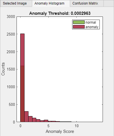
    Select the Anomaly Histogram tab to view the Anomaly Score vs. Counts histogram plot. Note the Anomaly Threshold of 0.0002963 on the anomaly histogram plot. Above this threshold, the detector classifies the test image as an anomaly.

    vad_2.png

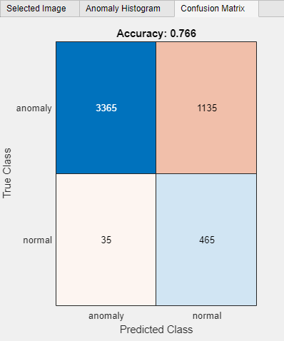
    Select the Confusion Matrix tab to view the performance of the trained anomaly detector. You can also use this matrix to set predicted and ground truth filters. The accuracy of 0.766 represents the ratio of correctly classified images to the total number of images in the data set.

    vad_3.png

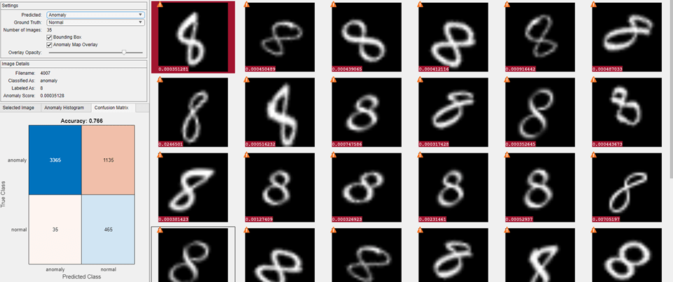
    Analyze the false positive images by setting the Predicted parameter to Anomaly and the Ground Truth parameter to Normal in the Settings pane. On each thumbnail of false positive images, the score appears against a red background because of the positive classification. The icon in the top left corner of the thumbnail is a yellow triangle with a white exclamation mark, which indicates the image is misclassified.

    vad_4.png

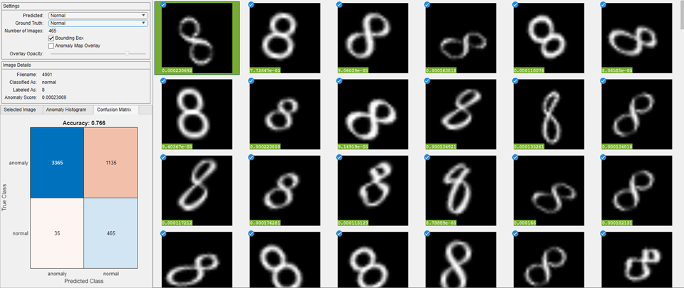
    Analyze the true negative images by setting the Predicted parameter to Normal and the Ground Truth parameter to Normal. On each thumbnail of true negative images, the score appears against a green background because of the negative classification. The icon in the top left corner of the thumbnail is a blue circle with a white checkmark, which indicates the image is correctly classified.

    vad7.png

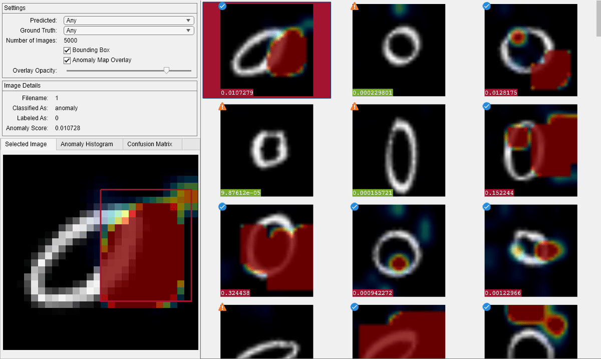
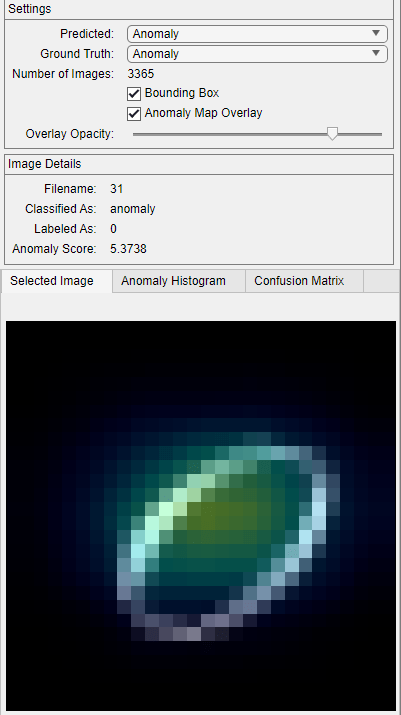
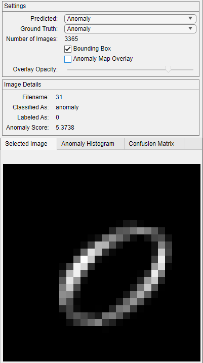
    Analyze the true positive images by setting the Predicted parameter to Anomaly and the Ground Truth parameter to Anomaly. Select the image with the filename 31. The anomaly map overlay displays the anomaly heatmap over the image. Clear Anomaly Map Overlay in the Settings pane and observe the difference in the Selected Image tab.
    vad_5.pngvad_6.png

    Input Arguments

    collapse all

    Anomaly detector, specified as an efficientADAnomalyDetector object, an fcddAnomalyDetector object, a fastFlowAnomalyDetector object, or a patchCoreAnomalyDetector object. You must set the Threshold property of the detector before calling this function.

    Images, specified as a datastore.

    Ground truth labels for each image, specified as a numeric vector, logical vector, or categorical vector. The viewAnomalyDetectionResults function converts the labels into a logical vector according to the set of anomaly labels in anomalyLabels.

    Predicted anomaly scores, returned as a numeric scalar, numeric vector, or formatted dlarray (Deep Learning Toolbox) object. scores contains one element for each image in I.

    Anomaly labels, specified as a vector of the same data type as gtLabels. When gtLabels is categorical, anomalyLabels can be of data type string whose values correspond to categories in gtLabels.

    The viewAnomalyDetectionResults function converts all ground truth labels in gtLabels that belong to the set of anomaly labels to a logical true, indicating an anomaly (positive detection). The function converts all other ground truth labels to a logical false, indicating normality (negative detection).

    More About

    collapse all

    Anomaly Detection Figure Window

    The viewAnomalyDetectionResults function opens an interactive figure window that enables you to explore the classification results and anomaly score maps for a set of images. Annotations on the image thumbnails can help you interpret the classification.

    • The number in the colored box indicates the overall anomaly score of the image. When the number is in a green box, the score is below the anomaly threshold and the image is predicted to be normal, or negative. When the number is in a red box, the score is above the anomaly threshold and the image is predicted to be anomalous, or positive.

    • The icon in the upper right corner indicates whether the predicted and ground truth classification agree. When the icon is a blue circle with a white check mark, the prediction and ground truth agree, and the prediction is a true positive or a true negative. When the icon is a yellow triangle with a white exclamation mark, the prediction and ground truth disagree, and the prediction is a false positive or false negative.

    Version History

    Introduced in R2022b

    expand all