Monocular Visual-Inertial SLAM
Simultaneous Localization and Mapping (SLAM) is a complex process that involves determining the position and orientation of a sensor, such as a camera, in relation to its surroundings. It also entails creating a map of the environment by identifying the 3D locations of various points. This example demonstrates how to effectively perform SLAM by combining images captured by a monocular camera with measurements obtained from an IMU sensor.
The method demonstrated in this example is inspired by ORB-SLAM3 which is a feature-based visual-inertial SLAM algorithm. The IMU and camera fusion is achieved using a factorGraph (Navigation Toolbox), which is a bipartite graph that consists of two types of nodes:
Variable Nodes: They represent the unknown random variables in an estimation problem such as the position of a mobile robot or a 3D point.
Factor Nodes: They represent a function which quantifies the relationship between the random variables. For example, a camera correspondence factor between 2D image points and 3D map points or an IMU measurement factor between two positions.
Factor graphs are a popular way of designing algorithms for sensor fusion-based SLAM because they provide an efficient and modular solution to SLAM problems and allow the graph to be easily updated if new measurements or constraints become available. Additionally, this type of model provides a flexible approach incorporating different types of sensors and data, including visual, lidar and inertial sensors, which makes it useful for variety of SLAM applications.
This example illustrates how to construct a monocular visual-inertial SLAM pipeline using a factor graph step by step.
Overview
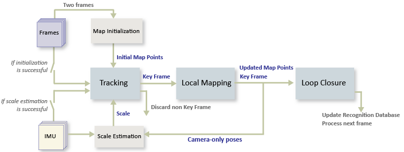
The visual-inertial SLAM pipeline includes the following steps:
Initial IMU Bias Estimation (Optional): If your data sequence contains a sufficient number of static frames, you can use them to estimate the IMU bias. This helps you initialize the factor graph later.
Map Initialization: Start by initializing the map of 3-D points from two video frames. The 3-D points and relative camera pose are computed using triangulation based on 2-D ORB feature correspondences.
Camera and IMU alignment: Once the map is initialized, generate a set of camera poses using Structure From Motion (SFM). Then use corresponding IMU measurements to align the camera and IMU frames and to find the scale conversion between the IMU and camera odometries.
Tracking: Once the camera and IMU data are aligned and scaled correctly, initialize the factor graph. Then, for each new key frame, estimate the camera pose by matching features in the current frame to features in the last key frame. Refine the estimated camera pose by tracking the local map. Then, add the camera poses to the factor graph with their corresponding IMU measurements.
Local Mapping: Use the current frame to create new 3-D map points if it is identified as a key frame. At this stage, the factor graph is optimized, and the camera poses and 3-D points are adjusted using a set of local key frames.
Loop Closure: Detect loops for each key frame by comparing the key frame against all previous key frames using the bag-of-features approach. Once a loop closure is detected, add a new link to the factor graph to reflect the connection found by the loop closure.
Download the Input Data Sequence
The data used in this demo has been extracted from the Blackbird data set (NYC Subway Winter). It represents a sequence from a UAV flying around in a simulated subway environment. Download the MAT file which contains the images, camera intrinsics and IMU measurements.
uavData = helperDownloadSLAMData();

images     = uavData.images;
intrinsics = uavData.intrinsics;
timeStamps = uavData.timeStamps;
Set up the noise parameters using the factorIMUParameters object. These values are typically provided by the IMU manufacturer.
imuParams = factorIMUParameters(SampleRate=100,GyroscopeNoise=0.1, ...
            GyroscopeBiasNoise=3e-3,AccelerometerNoise=0.3, ...
            AccelerometerBiasNoise=1e-3,ReferenceFrame="ENU");
Initial Bias Estimation
A section of the input data sequence has only static frames. These frames are useful for estimating the initial bias of the IMU sensor, which you can then use as a prior when we construct the factor graph. Accounting for the bias helps to reduce pose estimation errors because it can serve as an initial guess during the optimization. This step is optional, as it depends on the availability of static frames.
startBiasIdx  = 40; %  Index from which the bias estimation starts
startFrameIdx = 150; % Index from which the SLAM pipeline starts
initBias = helperEstimateInitialBias(uavData,startBiasIdx,startFrameIdx,imuParams);
Map Initialization
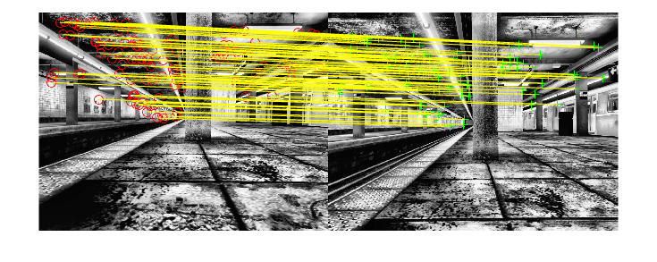
We start by initializing the map which holds the 3-D world points. This step is crucial and has a significant impact on the accuracy of final SLAM result. Find the initial ORB feature point correspondences using the matchFeatures function between a pair of images. After the correspondences are found, you can use these two geometric transformation models to establish map initialization:
Homography: If the scene is planar, a homography projective transformation is a better choice to describe feature point correspondences.
Fundamental Matrix: If the scene is non-planar, a fundamental matrix must be used instead.
The homography and the fundamental matrix can be computed using estgeotform2d and estimateFundamentalMatrix, respectively. The model that results in a smaller reprojection error is selected to estimate the relative rotation and translation between the two frames using estrelpose. Because the RGB images are taken by a monocular camera which does not provide the depth information, the relative translation can only be recovered up to a specific scale factor.
Given the relative camera pose and the matched feature points in the two images, the 3-D locations of the matched points are determined using triangulateMultiview function. A triangulated map point is valid when it is in the front of both cameras, when its reprojection error is low, and when the parallax of the two views of the point is sufficiently large.
% Set random seed for reproducibility
rng(0);

% Detect and extract ORB features
scaleFactor = 1.2;
numLevels   = 8;
numPoints   = 5000;
numSkipFrames = 20;
numPointsKeyFrame = 200;

currI = images{1, startFrameIdx};
[preFeatures, prePoints] = helperDetectAndExtractFeatures(currI, scaleFactor, numLevels, numPoints, intrinsics);

currFrameIdx = startFrameIdx + 1;
firstI       = currI; % Preserve the first frame

isMapInitialized  = false;

% Map initialization loop
while ~isMapInitialized && currFrameIdx < size(images,2)

    currI = images{currFrameIdx};

    [currFeatures, currPoints] = helperDetectAndExtractFeatures(currI, scaleFactor, numLevels, numPoints, intrinsics);

    currFrameIdx = currFrameIdx + 1;

    % Find putative feature matches
    indexPairs = matchFeatures(preFeatures, currFeatures, Unique=true, MaxRatio=0.5, MatchThreshold=80);

    % If not enough matches are found, check the next frame
    minMatches = 100;
    if size(indexPairs, 1) < minMatches
        continue
    end

    preMatchedPoints  = prePoints(indexPairs(:,1),:);
    currMatchedPoints = currPoints(indexPairs(:,2),:);

    % Compute homography and evaluate reconstruction
    [tformH, scoreH, inliersIdxH] = helperComputeHomography(preMatchedPoints, currMatchedPoints);

    % Compute fundamental matrix and evaluate reconstruction
    [tformF, scoreF, inliersIdxF] = helperComputeFundamentalMatrix(preMatchedPoints, currMatchedPoints);

    % Select the model based on a heuristic
    ratio = scoreH/(scoreH + scoreF);
    ratioThreshold = 0.45;
    if ratio > ratioThreshold
        inlierTformIdx = inliersIdxH;
        tform          = tformH;
    else
        inlierTformIdx = inliersIdxF;
        tform          = tformF;
    end

    % Computes the camera location up to scale. Use half of the
    % points to reduce computation
    inlierPrePoints  = preMatchedPoints(inlierTformIdx);
    inlierCurrPoints = currMatchedPoints(inlierTformIdx);
    [relPose, validFraction] = estrelpose(tform, intrinsics, ...
        inlierPrePoints(1:2:end), inlierCurrPoints(1:2:end));

    % If not enough inliers are found, move to the next frame
    if validFraction < 0.9 || numel(relPose)~=1
        continue
    end

    % Triangulate two views to obtain 3-D map points
    minParallax = 1; % In degrees
    [isValid, xyzWorldPoints, inlierTriangulationIdx] = helperTriangulateTwoFrames(...
        rigidtform3d, relPose, inlierPrePoints, inlierCurrPoints, intrinsics, minParallax);

    if ~isValid
        continue
    end

    % Get the original index of features in the two key frames
    indexPairs = indexPairs(inlierTformIdx(inlierTriangulationIdx),:);

    isMapInitialized = true;

    disp(['Map initialized with frame ', num2str(startFrameIdx),' and frame ', num2str(currFrameIdx-1)])
end % End of map initialization loop
Map initialized with frame 150 and frame 214
if isMapInitialized
    % Show matched features
    hfeature = showMatchedFeatures(firstI, currI, prePoints(indexPairs(:,1)), ...
        currPoints(indexPairs(:, 2)), "Montage");
else
    error('Unable to initialize the map.')
end
Store Initial Key Frames and Map Points
After the map is initialized using two frames, you can use imageviewset and worldpointset to store the two key frames and the corresponding map points:
imageviewsetstores the key frames and their attributes, such as ORB descriptors, feature points, camera poses, and graph connections between the key frames, such as feature points matches and relative camera poses. It also builds and updates a pose graph. The absolute camera poses and relative camera poses of odometry edges are stored asrigidtform3dobjects. The relative camera poses of loop-closure edges are stored asaffinetform3dobjects.worldpointsetstores 3-D positions of the map points and the 3-D to 2-D projection correspondences, indicating which map points are observed in a key frame and which key frames observe a map point. It also stores other attributes of map points, such as the mean view direction, the representative ORB descriptors, and the range of distance at which the map point can be observed.
% Create an empty imageviewset object to store key frames
vSetKeyFrames = imageviewset;

% Create an empty worldpointset object to store 3-D map points
mapPointSet   = worldpointset;

% Add the first key frame. Place the camera associated with the first
% key frame at the origin, oriented along the Z-axis
preViewId     = 1;
vSetKeyFrames = addView(vSetKeyFrames, preViewId, rigidtform3d, Points=prePoints,...
    Features=preFeatures.Features);

% Add the second key frame
currViewId    = 2;
vSetKeyFrames = addView(vSetKeyFrames, currViewId, relPose, Points=currPoints,...
    Features=currFeatures.Features);

% Add connection between the first and the second key frame
vSetKeyFrames = addConnection(vSetKeyFrames, preViewId, currViewId, relPose, Matches=indexPairs);

% Add 3-D map points
[mapPointSet, newPointIdx] = addWorldPoints(mapPointSet, xyzWorldPoints);

% Add observations of the map points
preLocations  = prePoints.Location;
currLocations = currPoints.Location;
preScales     = prePoints.Scale;
currScales    = currPoints.Scale;

% Add image points corresponding to the map points in the first key frame
mapPointSet   = addCorrespondences(mapPointSet, preViewId, newPointIdx, indexPairs(:,1));

% Add image points corresponding to the map points in the second key frame
mapPointSet   = addCorrespondences(mapPointSet, currViewId, newPointIdx, indexPairs(:,2));
Initialize Loop Closure Detection Database
Loop detection in this example is performed using the bags-of-words approach. You can create a visual vocabulary represented as a bagOfFeatures object offline using the ORB descriptors extracted from a large set of images in the dataset by calling:
bag = bagOfFeatures(imds,CustomExtractor=@helperORBFeatureExtractorFunction,TreeProperties=[3, 10],StrongestFeatures=1);
where imds is an imageDatastore object storing the training images and helperORBFeatureExtractorFunction is the ORB feature extractor function. See Image Retrieval with Bag of Visual Words for more information.
The loop closure process builds a database, by encode the incoming images into feature vectors compactly representing each view.
% Load the bag of features data created offline
bofData         = load("uavBoF.mat");
encodedImages   = [];

% Add features of the first two key frames to the database
encodedImages = [encodedImages; encode(bofData.bag,firstI,Verbose=false)];
encodedImages = [encodedImages; encode(bofData.bag,currI ,Verbose=false)];
Initialize the Factor Graph and Configure Trajectory and Map Visualization
Refine the initial reconstruction using a factorGraph (Navigation Toolbox), which optimizes both camera poses and world points to minimize the overall reprojection errors.
In MATLAB®, working with a factor graph involves managing a set of unique IDs for different parts of the graph, including: poses, 3D points or IMU measurements. By using these IDs, you can add additional constraints can be added between the variable nodes in the factor graph, such as the corresponding 2D image matches for a set of 3D points, or gyroscope measurements between two sets of poses. This is accomplished using factor nodes. You can generate unique IDs using the generateNodeID (Navigation Toolbox) function.
To initialize the factor graph, two pose variable nodes representing the first and second poses are combined with a factorCameraSE3AndPointXYZ (Navigation Toolbox) that represents the links between 2D feature points and 3D map points. At this stage, IMU measurements cannot be added to the graph yet, as the correct alignment and scaling of IMU data require several camera poses to be collected first.
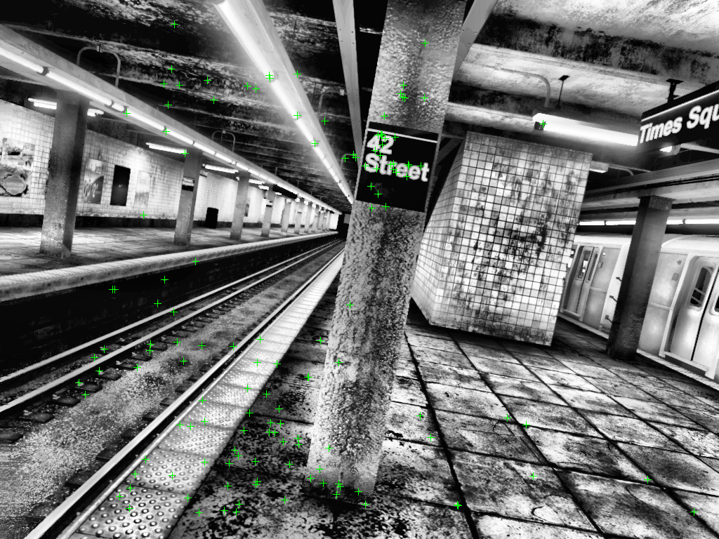
Once the initialization is successful, update the attributes of the map points including 3-D locations, view direction, and depth range. You can use helperVisualizeMotionAndStructure to visualize the map points and the camera locations.
% Initialize the factor graph
%   - viewToNode : array to convert imageViewSet indices to factorGraph pose id
%   - pointToNode: array to convert worldPointSet indices to factorGraph 3d point id
[fGraph, refinedAbsPoses, refinedPoints, viewToNode, pointToNode] = helperInitFactorGraph(vSetKeyFrames, mapPointSet, intrinsics);

% Update key frames with the refined poses
vSetKeyFrames = updateView(vSetKeyFrames, refinedAbsPoses);
vSetKeyFrames = updateConnection(vSetKeyFrames, preViewId, currViewId, relPose);

% Update map points with the refined positions
mapPointSet = updateWorldPoints(mapPointSet, newPointIdx, refinedPoints);

% Update view direction and depth
mapPointSet = updateLimitsAndDirection(mapPointSet, newPointIdx, vSetKeyFrames.Views);

% Update representative view
mapPointSet = updateRepresentativeView(mapPointSet, newPointIdx, vSetKeyFrames.Views);

% Update factor graph with refined poses
fgRefinedPose = double([refinedAbsPoses.AbsolutePose(1).Translation rotm2quat(refinedAbsPoses.AbsolutePose(1).R)]);
nodeState(fGraph,1,fgRefinedPose);
fgRefinedPose = double([refinedAbsPoses.AbsolutePose(2).Translation rotm2quat(refinedAbsPoses.AbsolutePose(2).R)]);
nodeState(fGraph,2,fgRefinedPose);

% Update factor graph with refined points
ptsIds = nodeIDs(fGraph,NodeType="POINT_XYZ");
nodeState(fGraph,ptsIds,refinedPoints);

% Visualize matched features in the current frame
close(hfeature.Parent.Parent);
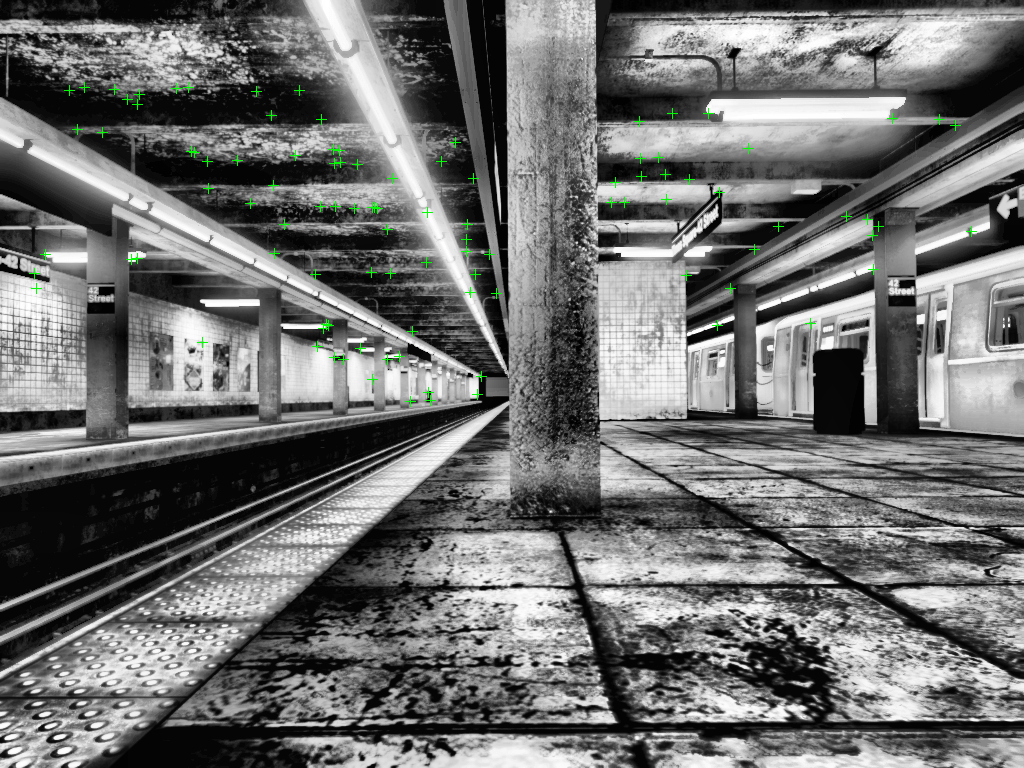
featurePlot   = helperVisualizeMatchedFeatures(currI, currPoints(indexPairs(:,2)));
% Visualize initial map points and camera trajectory
mapPlot       = helperVisualizeMotionAndStructureVI(vSetKeyFrames, mapPointSet);

showPlotLegend(mapPlot);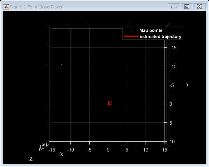
% ViewId of the current key frame
currKeyFrameId   = currViewId;

% ViewId of the last key frame
lastKeyFrameId   = currViewId;

% Index of the last key frame in the input image sequence
lastKeyFrameIdx  = currFrameIdx - 1;

% Indices of all the key frames in the input image sequence
addedFramesIdx   = [1; lastKeyFrameIdx];
IMU and Camera Alignment and Scaling
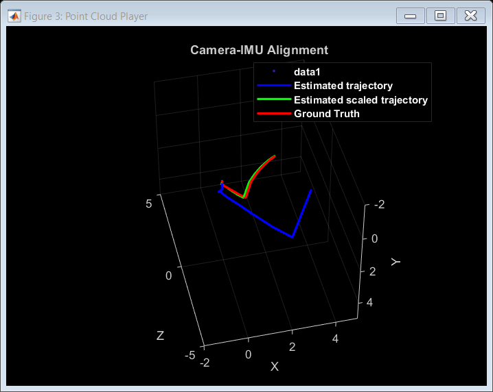
While using a monocular camera, pose estimates are obtained at an unknown scale, and differ from the metric measurements collected by an IMU. To address this issue, accelerometer measurements are used to estimate a scale factor which can scale the input camera poses to match the metric scale of the IMU measurements. In addition to that, you must align the reference frames of the input poses with the local navigation reference frame of the IMU to remove the constant gravity acceleration that is captured by the accelerometer can be removed. The estimateGravityRotationAndPoseScale function estimates both the scale and gravity rotation which you can use to improve the accuracy of the sensor fusion.
The frames used to obtain this alignment and scaling should be collected while keeping in mind a set of criteria:
Map initialization should be as accurate as possible, because it affects the camera poses greatly. Extracting a large number of features may be necessary to obtain great accuracy.
Camera poses should contain both static and moving frames, with the moving frames containing a strong acceleration in the gravity axis direction.
For efficiency, a sliding window should be used to store the poses. The window size should be kept relatively small to reduce the amount of scale drift in the poses.
Once the estimation has converged, update the poses on the factor graph by rotating and scaling them correctly. Also update the factor graph by setting the bias prior using the previously estimated value. Use the factorIMU (Navigation Toolbox) to link the corresponding IMU measurements to the previously stored poses. Finally, optimize the factor graph to adjust the poses and 3D points according to the newly added constrains. Use factorGraphSolverOptions (Navigation Toolbox) to set up the optimization parameters for the factor graph.
% Main loop
isLastFrameKeyFrame = true;
isIMUInitialized    = false;
isLoopClosed        = false;

keyTimeStamps   = [timeStamps.imageTimeStamps(startFrameIdx); timeStamps.imageTimeStamps(currFrameIdx-1)];
keyFrameToFrame = [startFrameIdx; currFrameIdx-1];  % Array to convert keyframe ids to frame id
biasToNode      = []; % Array to convert imageViewSet indices to factorGraph bias id
velToNode       = []; % Array to convert imageViewSet indices to factorGraph velocity id

loopCtr = 0; % Loop closure rolling window counter
scale   = 0; % Placeholder for IMU-Camera scale

% Factor graph optimization parameters
fgso = factorGraphSolverOptions;
fgso.MaxIterations           = 20;
fgso.VerbosityLevel          = 0;
fgso.FunctionTolerance       = 1e-5;
fgso.GradientTolerance       = 1e-5;
fgso.StepTolerance           = 1e-5;
fgso.TrustRegionStrategyType = 0;

while currFrameIdx < size(images,2)

    if ~isIMUInitialized && currKeyFrameId>50
        camPoses = poses(vSetKeyFrames);

        % Estimate the gravity rotation and pose scale that helps in transforming input camera poses to the
        % local navigation reference frame of IMU
        [gDir,scale] = helperAlignIMUCamera(camPoses,uavData,imuParams,...
            keyFrameToFrame,currKeyFrameId);

        if scale>0.3

            % Compare the scaled poses to the ground truth
            alignementPlot = helperDrawScaledandRotatedTraj(uavData,camPoses,scale,startFrameIdx,keyFrameToFrame);

            % Scale estimation was successful
            isIMUInitialized = true;

            xyzPoints1 = mapPointSet.WorldPoints;
            xyzPoints2 = nodeState(fGraph,nodeIDs(fGraph,NodeType="POINT_XYZ"));

            % Transform and scale the input camera poses and XYZ points using the estimated gravity direction and pose scale.
            [updatedCamPoses,updatedXYZPoints1,updatedXYZPoints2] = helperTransformToIMU(...
                camPoses,xyzPoints1,xyzPoints2,gDir,scale); %two sets of points because we can't remove nodes from graphs yet

            % Update mapPointSet and vSetKeyFrames
            vSetKeyFrames = updateView(vSetKeyFrames, updatedCamPoses);
            mapPointSet = updateWorldPoints(mapPointSet, (1:mapPointSet.Count), updatedXYZPoints1);

            % Update the poses and 3D points values in the factor graph
            for i=1:height(updatedCamPoses)
                pose = updatedCamPoses.AbsolutePose(i);
                nodeState(fGraph, viewToNode(i), double([pose.Translation rotm2quat(pose.R)]));
            end
            nodeState(fGraph,nodeIDs(fGraph,NodeType="POINT_XYZ"),updatedXYZPoints2);

            % Update the factor graph by linking the IMU mesurements
            veloId = generateNodeID(fGraph,length(viewToNode));
            biasId = generateNodeID(fGraph,length(viewToNode));

            velToNode  = [velToNode;veloId'];
            biasToNode = [biasToNode;biasId'];

            initVelPrior  = factorVelocity3Prior(velToNode(1));
            initBiasPrior = factorIMUBiasPrior(biasToNode(1));

            addFactor(fGraph,initVelPrior);
            addFactor(fGraph,initBiasPrior);

            nodeState(fGraph, biasToNode(1), initBias);

            for i=2:length(viewToNode)
                imuMeasurements = helperExtractIMUMeasurements(uavData, keyFrameToFrame(i-1), keyFrameToFrame(i));
                imuId = [viewToNode(i-1),velToNode(i-1),biasToNode(i-1), ...
                        viewToNode(i)  ,velToNode(i)  ,biasToNode(i)];
                fIMU = factorIMU(imuId,imuMeasurements.gyro,imuMeasurements.accel,imuParams,SensorTransform=uavData.camToIMUTransform);
                addFactor(fGraph,fIMU);
            end

            optimize(fGraph,fgso);

        end
    end
Tracking
To determine when to insert a new key frame, perform the tracking process for each frame using these steps:
Extract ORB features for each new frame and then match (using
matchFeatures), with features in the last key frame that have known corresponding 3-D map points.Estimate the camera pose with the Perspective-n-Point algorithm using
estworldpose.Using the camera pose, project the map points observed by the last key frame into the current frame and search for feature correspondences using
matchFeaturesInRadius.With 3-D to 2-D correspondence in the current frame, refine the camera pose by performing a motion-only bundle adjustment using factorGraph. Construct a factor graph using the steps in the previous section and then fix the 3D point nodes before proceeding to the optimization step.
Project the local map points into the current frame to search for more feature correspondences using
matchFeaturesInRadiusand refine the camera pose again using motion-only bundle adjustment.Determine if the current frame is a new key frame. If the current frame is a key frame, continue to the Local Mapping process. Otherwise, start Tracking for the next frame.
If tracking is lost because not enough number of feature points could be matched, try inserting new key frames more frequently.
    % Extract ORB features from the current image
    currI = images{1, currFrameIdx};
    [currFeatures, currPoints] = helperDetectAndExtractFeatures(currI, scaleFactor, numLevels, ...
        numPoints, intrinsics);

    % Track the last key frame
    [currPose, mapPointsIdx, featureIdx] = helperTrackLastKeyFrameVI(mapPointSet, ...
        vSetKeyFrames.Views, currFeatures, currPoints, lastKeyFrameId, intrinsics, scaleFactor);

    % Track the local map and check if the current frame is a key frame.
    [localKeyFrameIds, currPose, mapPointsIdx, featureIdx, isKeyFrame] = ...
        helperTrackLocalMapVI(mapPointSet, vSetKeyFrames, mapPointsIdx, ...
        featureIdx, currPose, currFeatures, currPoints, intrinsics, scaleFactor, numLevels, ...
        isLastFrameKeyFrame, lastKeyFrameIdx, currFrameIdx, numSkipFrames, numPointsKeyFrame);

    % Visualize matched features
    updatePlot(featurePlot, currI, currPoints(featureIdx));

    if ~isKeyFrame
        isLastFrameKeyFrame = false;
        currFrameIdx        = currFrameIdx + 1;
        continue
    else
        isLastFrameKeyFrame = true;
        keyFrameToFrame = [keyFrameToFrame; currFrameIdx];
        encodedImages   = [encodedImages; encode(bofData.bag,currI,Verbose=false)];
        keyTimeStamps   = [keyTimeStamps; timeStamps.imageTimeStamps(currFrameIdx)];
        loopCtr         = loopCtr+1;
    end


    % Update current key frame ID
    currKeyFrameId  = currKeyFrameId + 1;

    % Extract IMU measurements between two KFs
    imuMeasurements = helperExtractIMUMeasurements(uavData, keyFrameToFrame(end-1), keyFrameToFrame(end));

    % Add the new key frame and IMU data
    [fGraph, viewToNode, velToNode, biasToNode, mapPointSet, vSetKeyFrames] = helperAddNewKeyFrame(...
        fGraph, viewToNode, pointToNode, velToNode, biasToNode, mapPointSet, vSetKeyFrames, imuMeasurements, ...
        currPose, currFeatures, currPoints, mapPointsIdx, featureIdx, localKeyFrameIds, intrinsics, ...
        uavData.camToIMUTransform, imuParams, isIMUInitialized);

    % Remove outlier map points that are observed in fewer than 3 key frames
    [mapPointSet,pointToNode] = helperCullRecentMapPoints(mapPointSet, pointToNode, mapPointsIdx, newPointIdx);

    % Create new map points by triangulation
    minNumMatches = 10;
    minParallax   = 3;
    [fGraph, pointToNode, mapPointSet, vSetKeyFrames, newPointIdx] = helperCreateNewMapPointsVI(...
        fGraph, pointToNode, viewToNode, mapPointSet, vSetKeyFrames, ...
        currKeyFrameId, intrinsics, scaleFactor, minNumMatches, minParallax);
Loop Closure
Loop candidates are recognized by comparing feature descriptors, which represent encoded images using a pre-trained bag of words. The detected loop candidate is validated when it is located near a previous pose, and the distance between the feature descriptors associated to both poses is smaller than a set threshold.
When a valid loop candidate is found, use estgeotform3d to compute the relative pose between the loop candidate frame and the current key frame. Then add the loop connection with the relative pose to the factor graph.
    loopClosureCheck = 350; % Before this frame, loop closure does not occur.
    % Check loop closure after some key frames have been created
    if currKeyFrameId > loopClosureCheck && loopCtr>10

        % Minimum number of feature matches of loop edges
        loopEdgeNumMatches = 100;

        % Detect possible loop closure key frame candidates
        potentialLoopCandidates = helperFindPotentialLC(vSetKeyFrames);

        if ~isempty(potentialLoopCandidates)
            [isDetected, validLoopCandidates] = helperCheckLoopClosureVI(encodedImages, potentialLoopCandidates);
            if isDetected
                % Add loop closure connections
                [fGraph, isLoopClosed, mapPointSet, vSetKeyFrames] = helperAddLoopConnectionsVI(fGraph, viewToNode, pointToNode,...
                    mapPointSet, vSetKeyFrames, validLoopCandidates, currKeyFrameId, ...
                    currFeatures, currPoints, loopEdgeNumMatches, intrinsics);
                if isLoopClosed
                    loopCtr=0;
                end
            end
        end

    end
Local Mapping
Local mapping is performed for every key frame. When a new key frame is determined, add it and its corresponding IMU measurement to the factor graph and update to the mapPointSet and vSetKeyFrames objects. To ensure that mapPointSet contains as few outliers as possible, a valid map point must be observed in at least 3 key frames.
Create new map points by triangulating ORB feature points in the current key frame and its connected key frames. For each unmatched feature point in the current key frame, search for a match with other unmatched points in the connected key frames using matchFeatures. The local optimization of the factor graph refines the pose of the current key frame, the poses of connected key frames, and all the map points observed in these key frames.
    % Local bundle adjustment
    [refinedViews, dist] = connectedViews(vSetKeyFrames, currKeyFrameId, MaxDistance=2);
    refinedKeyFrameIds = refinedViews.ViewId;
    fixedViewIds = refinedKeyFrameIds(dist==2);
    fixedViewIds = fixedViewIds(1:min(10, numel(fixedViewIds)));

    refinedKeyFrameIds = [refinedKeyFrameIds; currKeyFrameId];

    [fGraph, solInfo] = helperLocalFactorGraphOptimization(fGraph, viewToNode, refinedKeyFrameIds, fixedViewIds);

    allOptNodes=solInfo.OptimizedNodeIDs;
    optPointNodes=setdiff(allOptNodes,viewToNode(refinedKeyFrameIds));
    [~,mapPointIdx]=intersect(pointToNode,optPointNodes,'stable');

    % Update world points
    mapPointSet = updateWorldPoints(mapPointSet,mapPointIdx,nodeState(fGraph,pointToNode(mapPointIdx)));

    % Update view poses
    for i=1:length(refinedKeyFrameIds)
        viewId = refinedKeyFrameIds(i);
        fgPose = nodeState(fGraph,viewToNode(viewId));
        absPose = rigidtform3d(quat2rotm(fgPose(4:7)),fgPose(1:3));
        vSetKeyFrames = updateView(vSetKeyFrames,viewId,absPose);
    end

    % Update view direction and depth
    mapPointSet = updateLimitsAndDirection(mapPointSet, mapPointIdx, vSetKeyFrames.Views);

    % Update representative view
    mapPointSet = updateRepresentativeView(mapPointSet, mapPointIdx, vSetKeyFrames.Views);

    % Visualize 3D world points and camera trajectory
    updatePlot(mapPlot, vSetKeyFrames, mapPointSet);

    % Update IDs and indices
    lastKeyFrameId  = currKeyFrameId;
    lastKeyFrameIdx = currFrameIdx;
    addedFramesIdx  = [addedFramesIdx; currFrameIdx]; %#ok<AGROW>
    currFrameIdx    = currFrameIdx + 1;

end % End of main loop
Loop edge added between keyframe: 49 and 361
Loop edge added between keyframe: 112 and 426
Loop edge updated between keyframe: 127 and 443
Loop edge added between keyframe: 143 and 462
Global Optimization
Once all the frames have been processed, we proceed to optimize the factor graph one last time by including all the keyframes, 3D points and IMU measurements.
% Optimize the poses
vSetKeyFramesOptim = vSetKeyFrames;
fGraphOptim = fGraph;

optimize(fGraphOptim,fgso);

% Update map points after optimizing the poses
for i=1:vSetKeyFrames.NumViews
    fgPose = nodeState(fGraphOptim,viewToNode(i));
    absPose = rigidtform3d(quat2rotm(fgPose(4:7)),fgPose(1:3));
    vSetKeyFramesOptim = updateView(vSetKeyFramesOptim,i,absPose);
end

mapPointSet = helperUpdateGlobalMap(mapPointSet,vSetKeyFrames,vSetKeyFramesOptim);

updatePlot(mapPlot, vSetKeyFrames, mapPointSet);

% Plot the optimized camera trajectory
plotOptimizedTrajectory(mapPlot, poses(vSetKeyFramesOptim))

% Update legend
showPlotLegend(mapPlot);

% Load ground truth
gTruth     = uavData.gTruth;

% Plot the actual camera trajectory
plotActualTrajectory(mapPlot, uavData, keyFrameToFrame, gDir);

% Show legend
showPlotLegend(mapPlot);
Comparison Against the Ground Truth
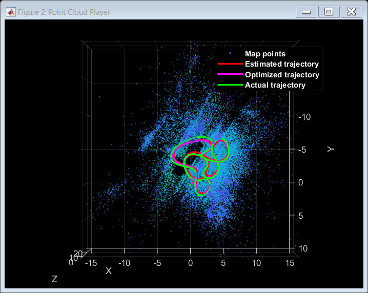
The downloaded data contains the gTruth array, which you can use to compare the obtained trajectory with the ground truth to qualitatively evaluate the accuracy of the SLAM pipeline. You can also calculate the root-mean-square-error (RMSE) and absolute-mean-error (AME) of trajectory estimates.
[rmse, ame] = helperGetAccuracy(poses(vSetKeyFramesOptim),uavData,keyTimeStamps,gDir);
    "AME for trajectory (m): "    "0.36203"

    "RMSE for trajectory (m): "    "0.26287"
In this example you learned how to utilize the factor graph to combine pose estimates from a camera with IMU measurements to obtain more accurate results.
Supporting Functions
Helper functions related to factor graph processing are included below.
Other functions are included in separate files. For more information on these functions, please refer to the Monocular Visual Simultaneous Localization and Mapping example.
helperAddLoopConnectionsVI adds connections between the current keyframe and the valid loop candidate.
helperCheckLoopClosureVI detects key frames that are loop candidates by retrieving visually similar images from the database.
helperCreateNewMapPointsVI creates new map points by triangulation.
helperTrackLastKeyFrameVI estimates the current camera pose by tracking the last key frame.
helperTrackLocalMapVI refines the current camera pose by tracking the local map.
helperDetectAndExtractFeatures detects and extracts and ORB features from the image.
helperComputeHomography computes homography and evaluates reconstruction.
helperComputeFundamentalMatrix computes fundamental matrix and evaluates reconstruction.
helperTriangulateTwoFrames triangulates two frames to initialize the map.
helperCullRecentMapPoints culls recently added map points.
helperUpdateGlobalMap updates 3-D locations of map points after pose graph optimization
helperAlignIMUCamera estimates the gravity rotation and pose scale to transform the input poses to the local navigation reference frame of IMU using IMU measurements and factor graph optimization.
helperTransformToIMU transforms and scales input poses and XYZ 3-D points according to specified gravity direction and pose scale.
helperLocalFactorGraphOptimization optimizes the factor graph using a set of local key frames.
helperInitFactorGraph initializes the factor graph using the results obtained from SfM.
function [fGraph, refinedAbsPoses, refinedPoints, viewToNode, pointToNode]  = helperInitFactorGraph(vSetKeyFrames, mapPointSet, intrinsics)

    K = intrinsics.K;
    camInfo = ((K(1,1)/1.5)^2)*eye(2);

    refinedKeyFrameIds = vSetKeyFrames.Views.ViewId';

    graphIds = [];
    graphMes = [];
    graphPts = [];

    fGraph = factorGraph;

    % Generate the necessary IDs for poses and 3D points
    zeroId      = generateNodeID(fGraph,1);
    viewToNode  = generateNodeID(fGraph,vSetKeyFrames.NumViews)';
    pointToNode = generateNodeID(fGraph,mapPointSet.Count)';

    mapPointIdx = [];

    % Extract the data from mapPointSet to initialize the factor graph
    for i=1:length(refinedKeyFrameIds)
      viewId=refinedKeyFrameIds(i);
      [pointIndices,featureIndices]=findWorldPointsInView(mapPointSet,viewId);

      pointIds = pointToNode(pointIndices);
      poseIds  = ones(length(pointIds),1)*viewToNode(viewId);
      graphIds = [graphIds; [poseIds pointIds]];

      ptsInView   = vSetKeyFrames.Views.Points{viewId,1}.Location;
      graphMes = [graphMes; ptsInView(featureIndices,:)];

      mapPointIdx = [mapPointIdx; pointIndices];
      graphPts = [graphPts; mapPointSet.WorldPoints(pointIndices,:)];
    end

    [mapPointIdx, uniqueIndex, ~] = unique(mapPointIdx);
    graphPts = graphPts(uniqueIndex,:);

    % Set up a pose prior using the initial position and fix it
    initPos = double([vSetKeyFrames.Views.AbsolutePose(1,1).Translation rotm2quat(vSetKeyFrames.Views.AbsolutePose(1,1).R)]);
    initPosePrior = factorPoseSE3Prior(viewToNode(1),Measurement=initPos);
    addFactor(fGraph,initPosePrior);
    fixNode(fGraph,viewToNode(1));

    % Set up a factorCameraSE3AndPointXYZ using the matches extracted above
    fCam=factorCameraSE3AndPointXYZ(graphIds, K, Measurement=graphMes, ...
    Information=camInfo);
    addFactor(fGraph,fCam);
    nodeState(fGraph,pointToNode(mapPointIdx),double(graphPts));

    % Set up a pose node using the current position
    pose=vSetKeyFrames.Views.AbsolutePose(2,1);
    pose=double([pose.Translation rotm2quat(pose.R)]);
    nodeState(fGraph,viewToNode(2),pose);

    % Fix a few 3D points for more stability
    ptsIDS = nodeIDs(fGraph,NodeType="POINT_XYZ");
    idx = randsample(height(ptsIDS'),int32(height(ptsIDS')*0.05));
    fixNode(fGraph,ptsIDS(idx));

    optimize(fGraph,factorGraphSolverOptions);

    fixNode(fGraph,ptsIDS(idx),false);

    % Extract the results of the factor graph optimization and re-package them
    poseIDs  = nodeIDs(fGraph,NodeType="POSE_SE3");
    fgposopt = nodeState(fGraph,poseIDs);

    initPose    = rigidtform3d(quat2rotm(fgposopt(1,4:7)),fgposopt(1,1:3));
    refinedPose = rigidtform3d(quat2rotm(fgposopt(2,4:7)),fgposopt(2,1:3));

    ViewId=[1;2];
    AbsolutePose=[initPose;refinedPose];

    refinedAbsPoses=table(ViewId,AbsolutePose);

    ptsIDS = nodeIDs(fGraph,NodeType="POINT_XYZ");
    refinedPoints = nodeState(fGraph,ptsIDS);
end
helperAddNewKeyFrame adds key frame data to the factor graph.
function [fGraph, viewToNode, velToNode, biasToNode, mapPoints, vSetKeyFrames] = helperAddNewKeyFrame(...
    fGraph, viewToNode, pointToNode, velToNode, biasToNode, mapPoints, vSetKeyFrames, imuMeasurements, ...
    cameraPose, currFeatures, currPoints, mapPointsIndices, featureIndices, keyFramesIndices, ...
    intrinsics, camToIMUTransform, imuParams, initIMU)

    N = length(mapPointsIndices);
    K = intrinsics.K;
    camInfo = ((K(1,1)/1.5)^2)*eye(2);

    viewId = vSetKeyFrames.Views.ViewId(end)+1;

    vSetKeyFrames = addView(vSetKeyFrames, viewId, cameraPose,...
        'Features', currFeatures.Features, ...
        'Points', currPoints);

    viewsAbsPoses = vSetKeyFrames.Views.AbsolutePose;

    % Generate the pose ID
    poseId = generateNodeID(fGraph,1);
    viewToNode = [viewToNode;poseId];

    for i = 1:numel(keyFramesIndices)
        localKeyFrameId = keyFramesIndices(i);
        [index3d, index2d] = findWorldPointsInView(mapPoints, localKeyFrameId);
        [~, index1, index2] = intersect(index3d, mapPointsIndices, 'stable');

        prePose   = viewsAbsPoses(localKeyFrameId);
        relPose = rigidtform3d(prePose.R' * cameraPose.R, ...
            (cameraPose.Translation-prePose.Translation)*prePose.R);

        if numel(index1) > 5
            vSetKeyFrames = addConnection(vSetKeyFrames, localKeyFrameId, viewId, relPose, ...
                Matches=[index2d(index1),featureIndices(index2)]);

            % Add a 3d pose factor to link both frames in the local map
            fgRelPose=double([relPose.Translation rotm2quat(relPose.R)]);
            fPose=factorTwoPoseSE3([viewToNode(localKeyFrameId) viewToNode(viewId)],Measurement=fgRelPose);
            addFactor(fGraph,fPose);
        end
    end

    mapPoints = addCorrespondences(mapPoints, viewId, mapPointsIndices, ...
        featureIndices);

    % Generate the IDs to be used in the factorCameraSE3AndPointXYZ
    ptsIds  = pointToNode(mapPointsIndices);
    poseIds = ones(N,1)*poseId;

    ptsInView = vSetKeyFrames.Views.Points{viewId,1}.Location;
    mesPts = ptsInView(featureIndices,:);

    % Add camera factor to the factor graph
    fCam = factorCameraSE3AndPointXYZ([poseIds ptsIds], K, Measurement=mesPts, ...
        Information=camInfo);
    addFactor(fGraph,fCam);

    % Add pose node to the factor graph
    pose = double([cameraPose.Translation rotm2quat(cameraPose.R)]);
    nodeState(fGraph,poseId,pose);

    % If the camera poses have been scaled properly, then add the IMU
    % factor to the factor graph
    if initIMU
        velId = generateNodeID(fGraph,1);
        velToNode=[velToNode;velId];

        biasId = generateNodeID(fGraph,1);
        biasToNode=[biasToNode;biasId];

        imuId = [viewToNode(end-1),velToNode(end-1),biasToNode(end-1), ...
                 viewToNode(end)  ,velToNode(end)  ,biasToNode(end)];
        fIMU = factorIMU(imuId,imuMeasurements.gyro,imuMeasurements.accel,imuParams,SensorTransform=camToIMUTransform);
        addFactor(fGraph,fIMU);
    end
end
References
[1] Dellaert, Frank, and Michael Kaess. Factor Graphs for Robot Perception. Now Publishers, 2017.
[2] Campos, Carlos, et al. “ORB-SLAM3: An Accurate Open-Source Library for Visual, Visual–Inertial, and Multimap SLAM.” IEEE Transactions on Robotics, vol. 37, no. 6, Dec. 2021, pp. 1874–90. DOI.org (Crossref), https://doi.org/10.1109/TRO.2021.3075644.