Modulate and Demodulate LTE Resource Grid
This example shows how to modulate and demodulate LTE resource grid samples. The model connects the LTE OFDM Modulator block to the LTE OFDM Demodulator block. To verify the algorithms of both the blocks, compare the output of the demodulator with the input of the modulator. You can generate HDL code from either block.
Generate the input resource grid using LTE Toolbox™.
enb = lteRMCDL('R.6');
enb.CyclicPrefix='Normal';
enb.TotSubframes = 1;

% --------------------------------------------------------------
%      NDLRB              |   Sampling Rate (MHz)
% --------------------------------------------------------------
%   	6                  |   R.4
%   	15                 |   R.5
%   	25                 |   R.6
%   	50                 |   R.7
%   	75                 |   R.8
%   	100                |   R.9
% --------------------------------------------------------------

[~,LTEGrid,info] = lteRMCDLTool(enb,[1;0;0;1]);

NDLRB=info.NDLRB;
if strcmp(enb.CyclicPrefix,'Normal')
    CPType=false;
else
    CPType=true;
end

sampling_time=1/30.72e6;
modulatorLatency=4137+2048*2;
demodulatorLatency=4137+2048*2;
stoptime=enb.TotSubframes*(30720+modulatorLatency+demodulatorLatency)*sampling_time;
Convert the LTEGrid sample frames to a stream of samples with control signals for input to the Simulink® model.
idlecyclesbetweensamples = 0;
idlecyclesbetweenframes  = 0;

[dataIn,ctrl] = whdlFramesToSamples(mat2cell(LTEGrid(:),numel(LTEGrid),1),...
                idlecyclesbetweensamples,idlecyclesbetweenframes);
validIn = logical(ctrl(:,3));
Run the Simulink model to modulate and demodulate the samples, and save the output samples to a workspace variable.
open_system('LTEHDLOFDMModDemodExample')
sim('LTEHDLOFDMModDemodExample');

rxgridSimulink = dataOut(validOut);

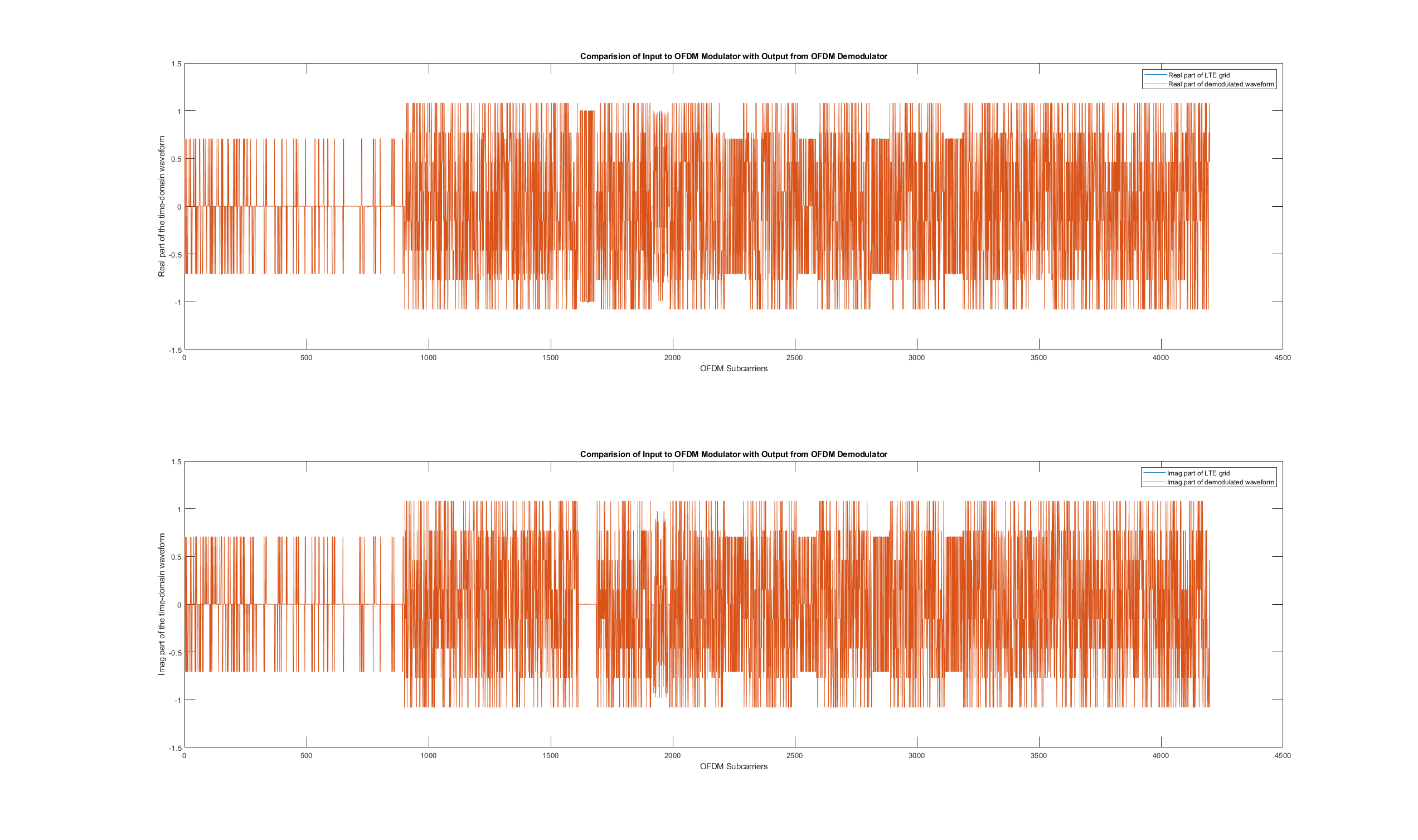
Compare the input of the modulator, generated from the lteRMCDLTool function, and the output of the demodulator from the model.
figure('units','normalized','outerposition',[0 0 1 1])
subplot(2,1,1);
plot(real(LTEGrid(:)));
hold on
plot(squeeze(real(rxgridSimulink)));
legend('Real part of LTE grid','Real part of demodulated waveform');
title('Comparision of Input to OFDM Modulator with Output from OFDM Demodulator');
xlabel('OFDM Subcarriers');
ylabel('Real part of the time-domain waveform');

subplot(2,1,2)
plot(imag(LTEGrid(:)))
hold on
plot(squeeze(imag(rxgridSimulink)))
legend('Imag part of LTE grid','Imag part of demodulated waveform');
title('Comparision of Input to OFDM Modulator with Output from OFDM Demodulator');
xlabel('OFDM Subcarriers');
ylabel('Imag part of the time-domain waveform');
