NR HDL SIB1 Recovery for FR2
This example shows how to design a 5G NR system information block 1 (SIB1) recovery model that is optimized for HDL code generation and hardware implementation and that supports frequency range 1 (FR1) and frequency range 2 (FR2).
Introduction
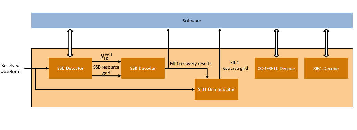
5G cell towers can operate in either FR1 or FR2 frequency bands. FR1 covers frequencies up to 6 GHz, and FR2 covers frequencies above 6 GHz, including the millimeter wave band. SIB1 recovery requires cell search, master information block (MIB) decoding, recovery of the SIB1 grid (the area of the resource grid containing CORESET0 and SIB1), and decoding of the CORESET0 PDCCH and SIB1 PDSCH from the SIB1 grid. The process of FR1 Cell Search and MIB recovery are described in the NR HDL Cell Search and NR HDL MIB Recovery examples respectively. The additional models used to implement FR1 SIB1 grid recovery, CORESET0 decoding, and SIB1 decoding are described in the Hardware Accelerators for NR SIB1 Recovery example. This example introduces functionality that is required to support FR2 and the process of upgrading an existing FR1 design.

The Simulink® models described in this example are fixed-point HDL-optimized implementations of SIB1 recovery for 5G NR FR1 and FR2. This example is one of a related set, for more information see NR HDL Reference Applications Overview.
File Structure
This example uses these files.
Simulink Models
nrhdlSIB1Recovery.slx: This Simulink model combines the processing of the SSB detector, SSB decoder, SIB1 demodulator, CORESET0 decoder, and SIB1 decoder into an integrated model illustrating the complete SIB1 grid recovery process. This model references thenrhdlDDCCore,nrhdlSSBDetectionCore,nrhdlSSBDecodingCore,nrhdlPolarDecodingChainCore,nrhdlGridDemodulationCore,nrhdlCORESET0DecodingCore, andnrhdlLDPCDecodingChainCoremodels.nrhdlDDCCore.slx: This model implements a DDC to create sample streams for SIB1 and SSBs.nrhdlSSBDetectionCore.slx: This model implements the SSB detection algorithm.nrhdlSSBDecodingCore.slx: This model implements the SSB decoding algorithm.nrhdlPolarDecodingChainCore.slx: This model implements the common polar decoding chain.nrhdlGridDemodulationCore.slx: This model implements the grid demodulation algorithm.nrhdlCORESET0DecodingCore.slx: This model implements the CORESET0 decoding algorithm.nrhdlLDPCDecodingChainCore.slx: This model implements the SIB1 LDPC decoding algorithm.
Simulink Data Dictionary
nrhdlReceiverData.sldd: This Simulink data dictionary contains bus objects that define the buses contained in the example models.
MATLAB Code
runNRSIB1RecoveryModel.m: This script uses the MATLAB reference to perform the search mode of the SSB detection algorithm, then runs thenrhdlSIB1RecoverySimulink model to demodulate and decode the SSB, and then demodulate the SIB1 grid. The script performs CORESET0 and SIB1 decoding using either MATLAB code designed for embedded software or the hardware accelerators in thenrhdlSIB1Recoverymodel.nrhdlexamples: Namespace containing the MATLAB reference code and utility functions for verifying the implementation models.
SSB Detection
This section describes the changes to the SSB detection MATLAB reference and Simulink implementation in the NR HDL Cell Search example that are required to support FR2.
The SSB detection algorithm performs search and demodulation with a given subcarrier spacing (SCS). The SCS options are 15 kHz or 30 kHz for FR1 and 120 kHz or 240 kHz for FR2. To add FR2 functionality, the new SCS options must be supported. The detector searches for SSBs by downsampling the received signal to one of the rates shown in the table according to the SCS. The signal is then cross-correlated with the PSS sequences.
    SCS (kHz)    Sample Rate (Msps)
    _________    __________________

        15              3.84
        30              7.68
       120             30.72
       240             61.44
To accommodate the increased bandwidth requirement of the SSBs in FR2, an input sampling rate of 61.44 Msps is used for the nrhdlSSBDetectionCore model (compared to 7.68 Msps for the FR1 design). The timing reference units are unchanged and still measured in samples at 61.44 Msps. The timing reference counters increment in steps of 16, 8, 2, and 1 for SCS of 15, 30, 120, and 240 kHz, respectively. The SCS selection subsystem inside nrhdlSSBDetection performs the first processing step for SSB detection. This subsystem creates the data streams for each SCS option by successively downsampling the data with halfband filters. All four streams are aligned, enabling the timing reference to be maintained when switching between different subcarrier spacings. The signal processing chain implemented in the nrhdlSSBDetectionCore is shown. A single SCS data stream is selected for downstream processing.

The selected SCS data stream is correlated against each of the three PSS sequences to detect SSBs. The FPGA implementation of these correlators in the time domain uses 144 DSPs. A frequency domain overlap-add method is used to minimize the DSP usage at the expense of a small increase in latency. This figure shows the overlap-add correlation in the nrhdlSSBDetectionCore model. The subsystem computes the four stages of the overlap-add method: FFT, multiplication by the three sets of frequency domain coefficients (one for each PSS), IFFT, and overlap and add of subsequent windows. This implementation uses one FFT, three complex multipliers, and three IFFTs, requiring 48 DSP blocks in total.

SSB Decoding
This section describes the changes to the SSB decoding MATLAB reference and Simulink implementation in the NR HDL MIB Recovery example that are required to support FR2.
The SSB decoding algorithm decodes the broadcast channel (BCH) contained in the SSB. The decoding process outputs the MIB and the beam index of the detected SSB. In FR1, the maximum number of SSBs that can be independently beamformed is 8. FR2 supports transmitting up to 64 SSBs, each on their own beam. The contents of the MIB between FR1 and FR2 differs to accommodate the increase in the maximum number of beams.
The nrhdlexamples.ssbDecode function and nrhdlSSBDecodingCore model accept Lmax as an input. Lmax is the maximum number of beams that can be transmitted by a cell tower, and its value depends on the carrier frequency. Valid settings for Lmax are 4 or 8 for FR1 and 64 for FR2. Lmax affects the descrambling in the BCH processing subsystem and how the final BCH payload is parsed.

Grid Demodulation
This section describes the changes to the SIB1 demodulation MATLAB reference and Simulink implementation in the Hardware Accelerators for NR SIB1 Recovery example that are implemented to support FR2.
The grid demodulation algorithm performs OFDM demodulation of the resource grid. The SCS options are 15 kHz or 30 kHz for FR1 and 60 kHz or 120 kHz for FR2. A 4096-point FFT which accepts two samples per cycle is used for all SCS options. The Subcarrier Spacing Selection subsystem creates the data streams for each SCS option by successively downsampling the data with halfband filters to the sample rates shown in the table. The SCS 120 KHz data stream is two samples per clock and the filter outputs for 15, 30 and 60 KHz are scalar. The scalar data streams are converted to two samples per cycle for compatibility with the FFT.
    SCS (kHz)    Sample Rate (Msps)
    _________    __________________

        15              61.44
        30             122.88
       120             245.76
       240             491.52
The Subcarrier Spacing Selection subsystem also includes the timing references for each SCS. The grid timing reference counts in samples at 491.52 MHz, corresponding to the maximum sample rate. The timing reference counters increment in steps of 8, 4, 2, and 1 for SCS of 15, 30, 60, and 120 kHz, respectively. The FR1 + FR2 variant of the Subcarrier Spacing Selection subsystem is shown.

The Configuration subsystem is updated to include additional lookup tables for generating the coreset0Resources and coreset0TimingOccasion signals for the FR2 use case. To support wideband grid demodulation the subsystem allows for the SCS, resource blocks and resource block offset to be specified by input port. This option allows for a generic portion of the wider resource grid to be demodulated, beyond the SIB1 subgrid. Additionally, the grid demodulation start time is adjusted from the CORESET0 timing occasion to the framehead following the SSB. The wideband grid demodulation runs continuously on the input data, until the stopDemod input is asserted.
To maintain time synchronization, timing updates can be provided via the timingUpdate and timingUpdateValid input ports. These timing updates represent the integer sample shift to be applied to the FFT window and are generated from the SSB detection algorithm running in repeat demodulation mode. Timing adjustments are applied on the subsequent framehead.
DDC
This section describes the changes to the DDC MATLAB reference and Simulink implementation in the NR HDL Cell Search example that are required to support FR2.
To accommodate the increased bandwidths of the SSBs and SIB1 in FR2, an input sampling rate of 491.52 Msps is used (compared to 61.44 Msps for the FR1 design). This input rate gives the receiver sufficient bandwidth to sample the SSB and SIB1 subcarriers, provided that the signal is centered on the SSBs. It also includes overhead for the coarse frequency search. This bandwidth allows for MIB and SIB1 recovery without retuning the center frequency of the frontend. To meet the throughput requirements and facilitate timing closure, the design uses a clock rate of 245.76 MHz with two samples per cycle.
The SSB DDC subsystem applies the given SSB frequency offset to the data stream, then filters and downsamples using three cascaded halfband filters. The first filter operates on the input data stream and downsamples to create an intermediate stream at 245.76 Msps. This downsample reduces the frame size from two samples per cycle to one. All downstream SSB processing is performed on scalar data, with the valid duty cycle reducing through each filtering stage. The next two filters perform the decimation to the final SSB data rate of 61.44 Msps. The SSB DDC/Filter and Downsample subsystem is shown.

The Grid DDC subsystem applies the given grid frequency offset to the data stream. The subsystem performs no filtering or downsampling as the downstream grid processing can operate on the full input signal bandwidth. The two signal paths, with independent NCOs for frequency mixing, allow the design to perform MIB recovery in parallel to SIB1 or wideband OFDM grid demodulation.
SIB1 Recovery Simulation Setup
The block diagram shows the simulation setup implemented by this example. The orange blocks highlight the comparison points between the MATLAB reference and the Simulink HDL implementation. The runNRSIB1RecoveryModel script runs the simulation, the MATLAB code represents the software control algorithm and the Simulink simulations perform the FPGA processing. 5G Toolbox™ functions are used to generate a test waveform. MATLAB reference code is used to perform the SSB search stage in place of running the Simulink simulation. The MATLAB reference provides equivalent results and improves simulation speed because it runs faster than the Simulink simulation. The results of the MATLAB SSB search is passed to both MATLAB and Simulink implementations of SIB1 recovery, and the output grids are directly compared. The Simulink SIB1 grid is decoded by one of two methods. The default option uses the nrhdlSIB1Recovery model to simulate the hardware accelerators for CORESET0 and SIB1 decoding. The second option uses a MATLAB-only decode algorithm. When the design is deployed to an SoC the first option reduces the computations performed by the embedded processor by offloading the calculations to the FPGA. The second option performs all processing in software allowing for the algorithm to be easily modified and updated without rebuilding the FPGA bitstream.

SIB1 Recovery Simulation
Use the runNRSIB1RecoveryModel script to run a SIB1 recovery simulation. The script displays its progress at the MATLAB command prompt, and produces plots of inputs and outputs for analysis. The script also supports multiple simulation cases. The full set of cases, and their parameters, are shown.
    Simulation Case    SSB Pattern    Subcarrier Spacing Common    PDCCH Config SIB1    SNR dB    Strongest SSB index    Lmax
    _______________    ___________    _________________________    _________________    ______    ___________________    ____

      "SimCase 1"       "Case D"                  60                      105             10               2              64
      "SimCase 2"       "Case E"                 120                       20              2               0              64
      "SimCase 3"       "Case A"                  15                      116              5               4               8
      "SimCase 4"       "Case C"                  30                        4             20               0               8
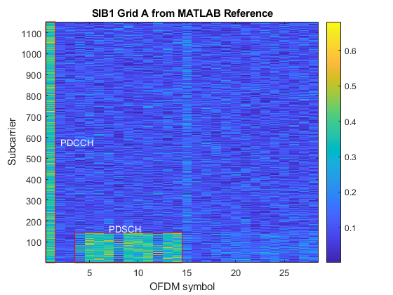
This example shows the results of running "SimCase 1". The resource grids produced by MATLAB and Simulink are displayed along with their relative mean squared error (MSE). This comparison verifies that the Simulink implementation closely matches the MATLAB reference. The grid plots are labeled to highlight the decoded PDCCH and PDSCH. The final stage of the script decodes CORESET0, displays the DCIs, and decodes SIB1. The result of the SIB1 decode is displayed, and the SIB1 bits from MATLAB and Simulink are compared to verify that they match.
runNRSIB1RecoveryModel;
Generating test waveform.
Selected Simulation case:

    Simulation Case    SSB Pattern    Subcarrier Spacing Common    PDCCH Config SIB1    SNR dB    Strongest SSB index    Lmax
    _______________    ___________    _________________________    _________________    ______    ___________________    ____

      "SimCase 1"       "Case D"                 60                       105             10               2              64

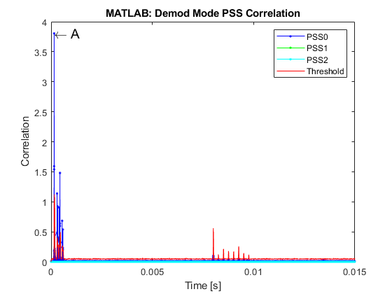
Searching for SSBs using the MATLAB reference.
    NCellID2    timingOffset    pssCorrelation    pssEnergy    frequencyOffset
    ________    ____________    ______________    _________    _______________

       0            8800            3.7746          4.0097          4329
       0           10992           0.44959         0.65759          2662
       0           17568            1.1373          1.3512          4987
       0           19760           0.91306          1.0926          3686
       0           24144           0.90225          1.1102          5880
       0           26336            1.4677          1.6633          4704
       0           32944           0.68088         0.87732          2085
       0           35136           0.53633         0.71313          2535

Recover the SIB1 grid using MATLAB reference.
Recovering the SIB1 grid using the MATLAB reference.
Recover the SIB1 grid using Simulink model.
Running nrhdlSIB1Recovery.slx
### Searching for referenced models in model 'nrhdlSIB1Recovery'.
### Total of 7 models to build.
### Starting serial model build.
### Model reference simulation target for nrhdlCORESET0DecodingCore is up to date.
### Model reference simulation target for nrhdlDDCCore is up to date.
### Model reference simulation target for nrhdlGridDemodulationCore is up to date.
### Model reference simulation target for nrhdlLDPCDecodingChainCore is up to date.
### Model reference simulation target for nrhdlPolarDecodingChainCore is up to date.
### Model reference simulation target for nrhdlSSBDecodingCore is up to date.
### Model reference simulation target for nrhdlSSBDetectionCore is up to date.

Build Summary

0 of 7 models built (7 models already up to date)
Build duration: 0h 0m 1.0801s
VarDim N, SF N, concat N, TLC YVarDim N, SF N, concat N, TLC YVarDim N, SF N, concat N, TLC YVarDim N, SF N, concat N, TLC YVarDim N, SF N, concat N, TLC YVarDim N, SF N, concat N, TLC Y..........

------------- Displaying Results for SIB1 grid A -------------

SSB demodulated at: 0.14323 ms

MATLAB and Simulink grids relative MSE : -60.884 dB

Extracting CORESET0 candidates from the SIB1 grid.
Decoding CORESET0 candidates using MATLAB reference.
Decoding CORESET0 candidates using Simulink.
Running nrhdlSIB1Recovery.slx
### Searching for referenced models in model 'nrhdlSIB1Recovery'.
### Total of 7 models to build.
### Starting serial model build.
### Model reference simulation target for nrhdlCORESET0DecodingCore is up to date.
### Model reference simulation target for nrhdlDDCCore is up to date.
### Model reference simulation target for nrhdlGridDemodulationCore is up to date.
### Model reference simulation target for nrhdlLDPCDecodingChainCore is up to date.
### Model reference simulation target for nrhdlPolarDecodingChainCore is up to date.
### Model reference simulation target for nrhdlSSBDecodingCore is up to date.
### Model reference simulation target for nrhdlSSBDetectionCore is up to date.

Build Summary

0 of 7 models built (7 models already up to date)
Build duration: 0h 0m 1.6407s
..........

DCI from MATLAB:
                     RIV: 1056
                TDDIndex: 0
    VRBToPRBInterleaving: 0
               ModCoding: 0
                      RV: 0
             SIIndicator: 0
                Reserved: 0

DCI from Simulink:
                     RIV: 1056
                TDDIndex: 0
    VRBToPRBInterleaving: 0
               ModCoding: 0
                      RV: 0
             SIIndicator: 0
                Reserved: 0

DCI successfully decoded from Simulink grid with hardware acceleration

Extracting LDPC codeword from the SIB1 grid.
Decoding SIB1 using MATLAB reference.
Decoding SIB1 using Simulink.
Running nrhdlSIB1Recovery.slx
### Searching for referenced models in model 'nrhdlSIB1Recovery'.
### Total of 7 models to build.
### Starting serial model build.
### Model reference simulation target for nrhdlCORESET0DecodingCore is up to date.
### Model reference simulation target for nrhdlDDCCore is up to date.
### Model reference simulation target for nrhdlGridDemodulationCore is up to date.
### Model reference simulation target for nrhdlLDPCDecodingChainCore is up to date.
### Model reference simulation target for nrhdlPolarDecodingChainCore is up to date.
### Model reference simulation target for nrhdlSSBDecodingCore is up to date.
### Model reference simulation target for nrhdlSSBDetectionCore is up to date.

Build Summary

0 of 7 models built (7 models already up to date)
Build duration: 0h 0m 0.544s
..........

SIB1 successfully decoded from Simulink grid with hardware acceleration
SIB1 bits from MATLAB and Simulink match


HDL Code Generation and Implementation Results
To generate the HDL code for this example, you must have the HDL Coder™ product. Use the makehdl and makehdltb commands to generate HDL code and an HDL test bench for the nrhdlSIB1Recovery/SIB1 Recovery subsystem. The resulting HDL code is synthesized for a Xilinx® Zynq® UltraScale+ RFSoC ZCU111 evaluation board. The table shows the post place and route resource utilization results. The design meets timing with a clock frequency of 245.76 MHz.
       Resource        Usage
    _______________    ______

    Slice Registers    148288
    Slice LUTs         100100
    RAMB18                426
    RAMB36                 36
    URAM                    8
    DSP48                 295
To deploy the nrhdlSIB1Recovery model to a hardware platform, see the Deploy NR HDL Reference Applications on FPGAs and SoCs example.