hornRidge
Create double-ridged rectangular horn
Description
The default hornRidge object creates a double-ridged horn
antenna resonating around 11GHz. The default dimensions for this antenna object are
chosen for an operating frequency range of 10 GHz-12 GHz.
Ridged horn antennas are commonly used in electromagnetic interference and compatibility applications for generating electromagnetic fields. These antennas are also used in radio astronomy or radar cross-section (RCS) measurements.
Creation
Description
ant = hornRidge
ant = hornRidge(PropertyName=Value)PropertyName is the property name and
Value is the corresponding value. You can specify
several name-value arguments in any order as
PropertyName1=Value1,...,PropertyNameN=ValueN.
Properties that you do not specify, retain their default values.
For example, ant = hornRidge(FlareLength=178.38e-3)
creates a ridged horn antenna object with a flare length of 178.39
millimeters.
Properties
Object Functions
axialRatio | Calculate and plot axial ratio of antenna or array |
bandwidth | Calculate and plot absolute bandwidth of antenna or array |
beamwidth | Beamwidth of antenna |
charge | Charge distribution on antenna or array surface |
current | Current distribution on antenna or array surface |
design | Create antenna, array, or AI-based antenna resonating at specified frequency |
efficiency | Calculate and plot radiation efficiency of antenna or array |
EHfields | Electric and magnetic fields of antennas or embedded electric and magnetic fields of antenna element in arrays |
feedCurrent | Calculate current at feed for antenna or array |
impedance | Calculate and plot input impedance of antenna or scan impedance of array |
info | Display information about antenna, array, or platform |
memoryEstimate | Estimate memory required to solve antenna or array mesh |
mesh | Generate and view mesh for antennas, arrays, and custom shapes |
meshconfig | Change meshing mode of antenna, array, custom antenna, custom array, or custom geometry |
msiwrite | Write antenna or array analysis data to MSI planet file |
optimize | Optimize antenna and array catalog elements using SADEA or TR-SADEA algorithm |
pattern | Plot radiation pattern of antenna, array, or embedded element of array |
patternAzimuth | Azimuth plane radiation pattern of antenna or array |
patternElevation | Elevation plane radiation pattern of antenna or array |
peakRadiation | Calculate and mark maximum radiation points of antenna or array on radiation pattern |
rcs | Calculate and plot monostatic and bistatic radar cross section (RCS) of platform, antenna, or array |
resonantFrequency | Calculate and plot resonant frequency of antenna |
returnLoss | Calculate and plot return loss of antenna or scan return loss of array |
show | Display antenna, array, AI-based antenna, platform, or shape |
sparameters | Calculate S-parameters for antenna or array |
stlwrite | Write mesh information to STL file |
vswr | Calculate and plot voltage standing wave ratio (VSWR) of antenna or array element |
Examples
Create and view a default double ridged horn antenna.
ant = hornRidge
ant =
  hornRidge with properties:

         NumFlares: 4
       FlareLength: 0.1784
        FlareWidth: 0.1834
       FlareHeight: 0.1732
            Length: 0.0538
             Width: 0.0370
            Height: 0.0177
       RidgeLength: 0.0370
        RidgeWidth: 0.0050
          RidgeGap: 0.0070
    FeedHoleRadius: 5.0000e-04
         FeedWidth: 1.0000e-04
        FeedOffset: [-0.0076 0]
         Conductor: [1×1 metal]
              Tilt: 0
          TiltAxis: [1 0 0]
              Load: [1×1 lumpedElement]
show(ant)

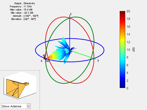
Plot the radiation pattern of the antenna at 11 GHz.
p = PatternPlotOptions(MagnitudeScale=[0 20]);
figure
pattern(ant,11e9,PatternOptions=p);
Create and view a ridged horn antenna with 2 flares.
ant = hornRidge(NumFlares=2)
ant =
  hornRidge with properties:

         NumFlares: 2
       FlareLength: 0.1784
        FlareWidth: 0.1834
       FlareHeight: 0.1732
            Length: 0.0538
             Width: 0.0370
            Height: 0.0177
       RidgeLength: 0.0370
        RidgeWidth: 0.0050
          RidgeGap: 0.0070
    FeedHoleRadius: 5.0000e-04
         FeedWidth: 1.0000e-04
        FeedOffset: [-0.0076 0]
         Conductor: [1×1 metal]
              Tilt: 0
          TiltAxis: [1 0 0]
              Load: [1×1 lumpedElement]
show(ant)

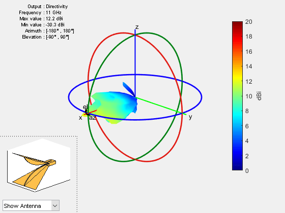
Plot the radiation pattern of the antenna at 11 GHz.
p = PatternPlotOptions(MagnitudeScale=[0 20])
p =
  PatternPlotOptions with properties:

      Transparency: 1
         SizeRatio: 0.9000
    MagnitudeScale: [0 20]
     AntennaOffset: [0 0 0]
figure
pattern(ant,11e9,PatternOptions=p)
Version History
Introduced in R2020b