Electrostatic Speaker Modeling with Simscape Acoustics
R2026bThis example shows how to model an electrostatic loudspeaker using the Simscape™ Acoustics library. The model captures the electrical, mechanical, and acoustic behavior of a push-pull electrostatic transducer with a circular diaphragm that is 14 cm in diameter.
Introduction
An electrostatic loudspeaker uses electrostatic force to drive a thin, lightweight diaphragm suspended between two perforated stator plates. A DC bias voltage establishes a static electric field across the air gaps. When an audio signal is applied through a step-up transformer, it modulates the electric field differentially on each side of the diaphragm, producing a net force that moves the diaphragm and radiates sound.
Electrostatic speakers are valued for their low distortion, excellent transient response, and wide, uniform dispersion. Their lightweight diaphragm has much less mass than a conventional moving coil cone, enabling fast and accurate tracking of the input signal. The push-pull configuration ensures that the net force on the diaphragm is approximately linear with the audio signal voltage, reducing harmonic distortion.
System Architecture
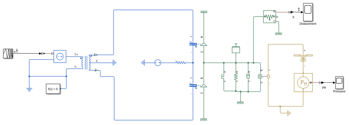
The electrostatic speaker model consists of three main domains:
Electrical domain - A DC bias voltage source provides the polarizing voltage. A controlled voltage source supplies the audio signal, which is stepped up by a center-tapped transformer to drive the two stator plates with opposing polarity signals.
Mechanical domain - The diaphragm is modeled as a mass-spring-damper system with a translational hard stop to limit diaphragm excursion to the electrode gap.
Acoustic domain - The diaphragm velocity is coupled to acoustic volume velocity through a mechanical-to-acoustic converter. Radiation impedance loading and far-field pressure sensing complete the acoustic chain.
Open the model.
model = "electrostaticSpeaker";
open_system(model);
Model Components
The model uses the following key components:
Variable Gap Capacitor - Two instances model the air-gap capacitors formed between the diaphragm and each stator plate. These blocks capture the electromechanical coupling by relating the electrostatic force to the applied voltage and the instantaneous gap distance. As the diaphragm moves, the capacitance changes, producing a position-dependent force.
Center-Tapped Transformer - Steps up the audio signal voltage and splits it into two out-of-phase signals that drive the two stators differentially, providing the high voltage needed for electrostatic drive.
DC Voltage Source - Provides the bias voltage that polarizes the diaphragm, establishing the static electric field required for electrostatic operation.
Mass - Represents the diaphragm mass, which is much lighter than a typical moving coil speaker cone.
Translational Spring - Models the diaphragm tension.
Translational Damper - Models mechanical losses in the diaphragm suspension.
Translational Hard Stop - Limits diaphragm displacement, preventing the diaphragm from contacting the stator plates.
Mechanical-to-Acoustic Converter - Couples diaphragm velocity to acoustic volume velocity through the effective radiating area.
Radiation Impedance - Circular Piston - Models the acoustic radiation loading on the diaphragm, accounting for the frequency-dependent resistive and reactive components of radiation impedance.
Far-Field Pressure Sensor - Computes the radiated sound pressure at a reference distance from the diaphragm.
A high-value resistor provides a DC path for the bias circuit while effectively blocking audio frequencies.
Simulation
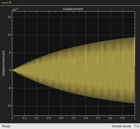
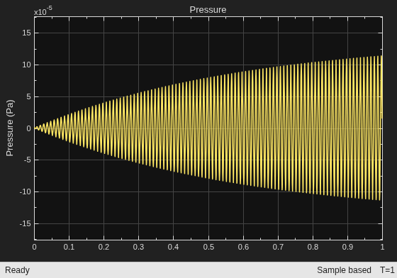
Simulate the model. The input is a chirp signal that sweeps across the audio frequency range. The scopes display the diaphragm displacement and the radiated far-field pressure.
sim(model);
Results
The Displacement scope shows the diaphragm excursion over time as the chirp sweeps in frequency. The Pressure scope shows the resulting far-field sound pressure at 1 m.
The electrostatic drive mechanism produces a force proportional to the product of the bias voltage and the audio signal voltage. Because both stators are driven differentially, the net force on the diaphragm is linear with the audio signal, which is the key advantage of the push-pull electrostatic configuration. The hard stop prevents the diaphragm from collapsing onto a stator plate if the signal amplitude becomes too large.
close_system(model,0)
References
[1] Peter J. Walker, "Wide range electrostatic loudspeakers," Wireless World, 61(5) pp. 208-211; 61(6) pp. 265-269; 61(8) pp. 381-384, 1955.
[2] Peter J. Walker, "New Developments in Electrostatic Loudspeakers," J. Audio Eng. Soc., 28(11), 1980, pp. 795-799.
[3] Leo Beranek and Tim Mellow, "Electrostatic Loudspeakers," Ch. 15 in Acoustics: Sound Fields, Transducers and Vibrations, 2nd ed. Academic Press, New York, 2019.
Acknowledgments
The original version of this model was authored by Dr. Stephen C. Thompson of Penn State University.
Copyright 2026 The MathWorks, Inc.
See Also
Mechanical to Acoustic Converter | Circular Piston Radiation Impedance | Far-Field Pressure Sensor

