ofdmChannelResponse
Syntax
Description
hest = ofdmChannelResponse(pathgains,pathfilters,nfft,cplen)nfft and cyclic prefix length equal to
cplen. The channel is specified by pathgains and
pathfilters. For more information, see OFDM Channel Response.
Examples
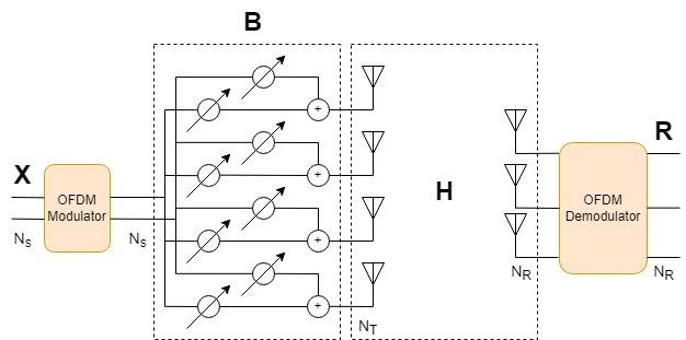
Obtain the channel response for a beamformed OFDM signal with parallel data streams filtered through an -by- MIMO channel. Use the channel response to apply OFDM equalization to the received OFDM-demodulated signal.
Define simulation variables.
rng(1);
numStreams = 2;  % Number of parallel data streams (Ns)
numTx = 4;       % Number of transmit antennas (Nt)
numRx = 3;       % Number of receive antennas (Nr)
bps = 6;         % Bits per QAM symbol (and OFDM data subcarrier)
nfft = 256;      % FFT length
cpLen = 16;      % Cyclic prefix length
numOFDMSym = 10; % Number of OFDM symbols
SNRdB = 40;      % Signal-to-noise ratio
Check that the number of data streams is no greater than either the number of transmit antennas or the number of receive antennas.
if numStreams > min(numTx,numRx)
    error('numStreams must be equal to or less than numTx and numRx.');
end
Configure OFDM subcarriers.
ofdmNullIdx = ...   % Guard bands and DC subcarrier
    [1:9 (nfft/2+1) (nfft-8+1:nfft)]';
numDataSC = ...     % Number of data subcarriers
    nfft-length(ofdmNullIdx);
Generate an array of data symbols consisting of parallel data streams, QAM-modulate the symbols, and then OFDM-modulate the QAM-modulated symbols.
dataBits = randi([0,1],[numDataSC*bps numOFDMSym numStreams]);
M = 2^bps; % Modulation order
qamTx = qammod(dataBits,M, ...
    InputType="bit", ...
    UnitAveragePower=true);
ofdmOut = ofdmmod(qamTx,nfft,cpLen,ofdmNullIdx);
Beamforming expands the dimensionality of the transmit signal to improve link performance over multipath channels. The data streams are fed through a beamformer that focuses the transmit energy over an -by-1 transmit antenna array where the number of antennas .
Form a beamformer matrix from steering vectors acting on each stream.
% Beamform the transmitted signal
fc = 1e9;
lambda = physconst('LightSpeed')/fc;
beamAngles = 15;
antIdx = (0:numTx-1);
antDelay = 2*pi*sin(2*pi*beamAngles*(0:numStreams-1).'/360)/lambda;
B = exp(1i*antIdx.*antDelay);  % Ns x Nt beamformer matrix
txOut = ofdmOut * B;
Filter the OFDM-modulated signal through a MIMO channel to get the channel coefficients.
mimoChannel = comm.MIMOChannel( ...
    SampleRate=1e6, ...
    PathDelays=[0 3e-6 5e-6], ...
    AveragePathGains=[0 0.5 0.2], ...
    MaximumDopplerShift=0, ...
    SpatialCorrelationSpecification="None", ...
    NumTransmitAntennas=numTx, ...
    NumReceiveAntennas=numRx, ...
    PathGainsOutputPort=true);
[channelOut,pathGains] = mimoChannel(txOut);
In a practical system, the channel must be sounded to estimate the channel response. Instead of sounding, the ofdmChannelResponse function computes the exact channel response using the path gains and path filters that are available after you pass data through the MIMO channel System object. Use channel path gains returned by the MIMO channel object, and the path filters and timing offset returned by the info object function, to obtain the OFDM channel response. If , the channel forms an over-determined system (there are more receive antennas than necessary to adequately decode the transmitted signals). Call ofdmChannelResponse with the pathGains from the MIMO channel function to get the channel response.
mimoChannelInfo = info(mimoChannel);
pathFilters = mimoChannelInfo.ChannelFilterCoefficients;
toffset = mimoChannelInfo.ChannelFilterDelay;
h = ofdmChannelResponse(pathGains,pathFilters,nfft,cpLen, ...
    setdiff(1:nfft,ofdmNullIdx),toffset); % Nsc x Nsym x Nt x Nr

[rxIn,nVar] = awgn(channelOut,SNRdB,"measured");
Before demodulating the OFDM signal, account for the timing offset and symbol offset, remove the initial samples, and then pad with zeros to keep the signal length unchanged.
zeropadding = zeros(toffset,numRx);
ofdmDemodIn = [rxIn(toffset+1:end,:); zeropadding];
symOffset = cpLen/2;
OFDM-demodulate and equalize the received signal.
rxSym = ofdmdemod(ofdmDemodIn,nfft,cpLen,symOffset,ofdmNullIdx);
The effects of beamforming and the MIMO channel affect the received data streams. The effective channel () is an -by- matrix defined as the product of the transmit beamformer and the MIMO channel coefficients.
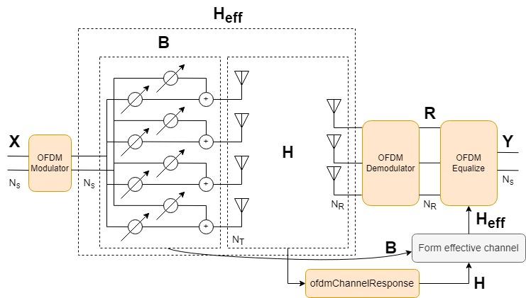
To use the OFDM channel response when equalizing the OFDM-demodulated signal, you must reshape the -by--by--by- array to an -by--by- array. Form the effective channel using the beamformer matrix B and the reshaped channel coefficients h. Equalize the received OFDM signal using the calculated effective channel, the noise variance, and the MMSE algorithm.
hReshaped = reshape(h,[],numTx,numRx);

hEff = zeros(numDataSC*numOFDMSym,numStreams,numRx);
for k = 1:numOFDMSym*numDataSC
    hEff(k,:,:) = B * squeeze(hReshaped(k,:,:));
end

eqSym = ofdmEqualize(rxSym,hEff,nVar);
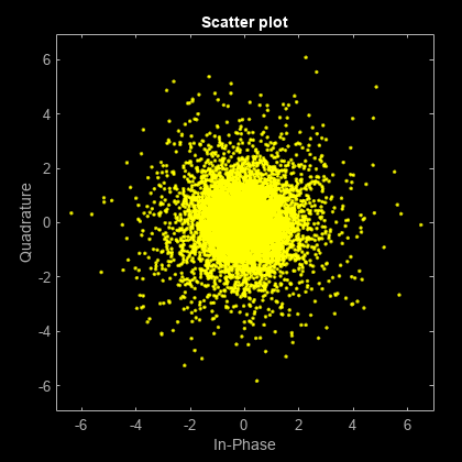
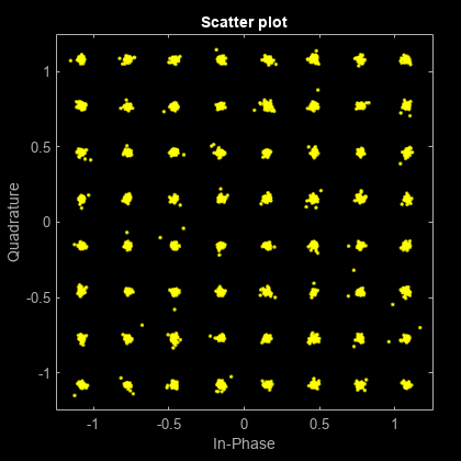
Show the received OFDM-demodulated symbols (rxSym) and the equalized OFDM-demodulated symbols (eqSym). The constellation of the OFDM-demodulated symbols before equalization does not resemble the QAM constellation. After equalization, the constellation points lay near the reference constellation.
figure(1);
scatterplot(rxSym(:));
figure(2);
scatterplot(eqSym(:));
Input Arguments
Output Arguments
More About
Algorithms
The OFDM channel response algorithm uses an FFT to compute the channel estimates by using the path gains and path filter coefficients available after you pass data through a MIMO channel. Use channel path gains returned by the MIMO channel object, and the path filters and timing offset returned by the info object function, to estimate the OFDM channel response.
This figure shows one OFDM symbol in addition to the input channel impulse and the output channel impulse response. The algorithm ignores samples outside the OFDM symbol.
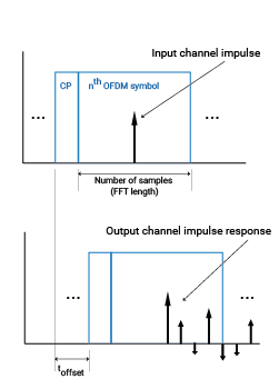
For a time-varying channel, such as most fading channels, the impulse response depends on the location of the impulse at the channel input.