SISO Fading Channel
Filter input signal through SISO multipath fading channel
Libraries:
Communications Toolbox /
Channels
Description
The SISO Fading Channel block filters an input signal using a single-input/single-output (SISO) multipath fading channel. This block models both Rayleigh and Rician fading. For processing details, see the Algorithms section.
Examples
Multipath Fading Channel in Simulink
Simulate multipath Rayleigh and Rician fading channels by using the SISO Fading Channel block.
Ports
Input
in — Input data signal
vector
Input data signal, specified as an NS-by-1 vector. NS represents the number of samples in the input signal.
Data Types: double
| single
Complex Number Support: Yes
Output
Out1 — Output data signal for fading channel
vector
Output data signal for the fading channel, returned as an NS-by-1 vector. NS represents the number of samples in the input signal.
Gain — Discrete path gains
matrix
Discrete path gains of the underlying fading process, returned as an NS-by-NP matrix.
NS represents the number of samples in the input signal.
NP represents the number of channel paths.
Dependencies
To enable this port, on the Main tab, select Output channel path gains.
Delay — Channel filter delay
scalar
Channel filter delay, returned as a scalar.
Dependencies
To enable this port, on the Main tab, select Output channel filter delay.
Parameters
To edit block parameters interactively, use the Property Inspector. From the Simulink® Toolstrip, on the Simulation tab, in the Prepare gallery, select Property Inspector.
Main Tab
Multipath parameters (frequency selectivity)Inherit sample rate from input — Option to inherit the sample rate from input
on (default) | off
Select this parameter to use the sample rate of the input signal when processing. When you select Inherit sample rate from input, the sample rate is NS/TS, where NS is the number of input samples, and TS is the model sample time.
Sample rate (Hz) — Input signal sample rate
1
(default) | positive scalar
Input signal sample rate in hertz, specified as a positive scalar. To match the model settings, set the sample rate to NS/TS, where NS is the number of input samples, and TS is the model sample time.
Dependencies
This parameter appears when Inherit sample rate from input is not selected.
Discrete path delays (s) — Delays for each discrete path
0
(default) | nonnegative scalar | row vector
Delays for each discrete path in seconds, specified as a nonnegative scalar or row vector.
When you set Discrete path delays (s) to a scalar, the SISO channel is frequency flat.
When you set Discrete path delays (s) to a vector, the SISO channel is frequency selective.
Average path gains (dB) — Average gain for each discrete path
0
(default) | scalar | row vector
Average gain for each discrete path in decibels, specified as a scalar or row vector. Average path gains (dB) must have the same size as Discrete path delays (s).
Normalize average path gains to 0 dB — Option to normalize average path gains to 0 dB
on (default) | off
Select this parameter to normalize the fading processes so that the total power of the path gains, averaged over time, is 0 dB.
Fading distribution — Fading distribution of channel
Rayleigh
(default) | Rician
Select the fading distribution of the channel, either
Rayleigh
or Rician
.
K-factors — K-factor of Rician fading channel
3
(default) | positive scalar | row vector of nonnegative values
K-factor of a Rician fading channel, specified as a positive scalar or a 1-by-NP vector of nonnegative values. NP equals the value of the Discrete path delays (s) parameter.
If you set K-factors to a scalar, the first discrete path is a Rician fading process with a Rician K-factor of K-factors. Any remaining discrete paths are independent Rayleigh fading processes.
If you set K-factors to a row vector, the discrete path corresponding to a positive element of the K-factors vector is a Rician fading process with a Rician K-factor specified by that element. The discrete path corresponding to any zero-valued elements of the K-factors vector are Rayleigh fading processes. At least one element value must be nonzero.
Dependencies
This parameter appears when you set Fading
distribution to Rician
.
LOS path Doppler shifts (Hz) — Doppler shifts for line-of-sight components
0
(default) | scalar | row vector
Doppler shifts for the line-of-sight components of the Rician fading channel in hertz, specified as a scalar or row vector. This parameter must have the same size as K-factors.
If you set LOS path Doppler shifts (Hz) to a scalar, it represents the line-of-sight component Doppler shift of the first discrete path that is a Rician fading process.
If you set LOS path Doppler shifts (Hz) to a row vector, the discrete path that is a Rician fading process has its line-of-sight component Doppler shift specified by the elements of LOS path Doppler shifts (Hz) that correspond to positive elements in the K-factors vector.
Dependencies
This parameter appears when you set Fading
distribution to Rician
.
LOS path initial phases (rad) — Initial phases for line-of-sight components
0
(default) | scalar | row vector
Initial phases for the line-of-sight component of the Rician fading channel in radians, specified as a scalar or row vector. This parameter must have the same size as K-factors.
If you set LOS path initial phases (rad) to a scalar, it is the line-of-sight component initial phase of the first discrete path that is a Rician fading process.
If you set LOS path initial phases (rad) to a row vector, the discrete path that is a Rician fading process has its line-of-sight component initial phase specified by the elements of LOS path initial phases (rad) that correspond to positive elements in the K-factors vector.
Dependencies
This parameter appears when you set Fading
distribution to Rician
.
Maximum Doppler shift (Hz) — Maximum Doppler shift for all channel paths
0.001
(default) | nonnegative scalar
Maximum Doppler shift for all channel paths in hertz, specified as a nonnegative scalar.
Maximum Doppler shift (Hz) must be less than or equal to (fs/10)/fc for each path. fs is the sampling rate at the input to this block. fc is the cutoff frequency factor of the path. For more information, see Cutoff Frequency Factor.
Doppler spectrum — Doppler spectrum shape for all channel paths
doppler('Jakes')
(default) | doppler('Flat')
| doppler('Rounded', ...)
| doppler('Bell', ...)
| doppler('Asymmetric Jakes', ...)
| doppler('Restricted Jakes', ...)
| doppler('Gaussian', ...)
| doppler('BiGaussian', ...)
Doppler spectrum shape for all channel paths, specified as a single Doppler spectrum
structure returned from the doppler
function or a
1-by-NP cell array of such structures. The default
value of this parameter is the Jakes Doppler spectrum (doppler('Jakes')
).
If you assign a single call to
doppler
, all paths have the same specified Doppler spectrum.If you assign a 1-by-NP cell array of calls to
doppler
using any of the specified syntaxes, each path has the Doppler spectrum specified by the corresponding Doppler spectrum structure in the array. In this case, NP equals the value of the Discrete path delays (s) parameter.
Dependencies
This parameter applies when you set Maximum Doppler shift (Hz) to a value greater than zero.
Initial seed — Random number generator initial seed
73
(default) | nonnegative integer
Random number generator initial seed for this block, specified as a nonnegative integer.
Output channel path gains — Option to output channel path gains
off (default) | on
Select this parameter to add the Gain output port to the block and output the channel path gains of the underlying fading process.
Output channel filter delay — Option to output channel filter delay
off (default) | on
Select this parameter to add the Delay output port to the block and output the channel filter delay of the underlying fading process.
Simulate using — Compilation type
Interpreted execution
(default) | Code generation
Compilation type, specified as Interpreted execution
or
Code generation
.
Interpreted execution
— Simulate model using the MATLAB® interpreter. This option shortens startup time but has slower simulation speed thanCode generation
.Code generation
— Simulate model using generated C code. The first time you run a simulation, Simulink generates C code for the block. The C code is reused for subsequent simulations, as long as the model does not change. This option requires additional startup time but provides faster simulation speed thanInterpreted execution
.
Visualization Tab
Channel visualization — Select the channel visualization
Off
(default) | Impulse response
| Frequency response
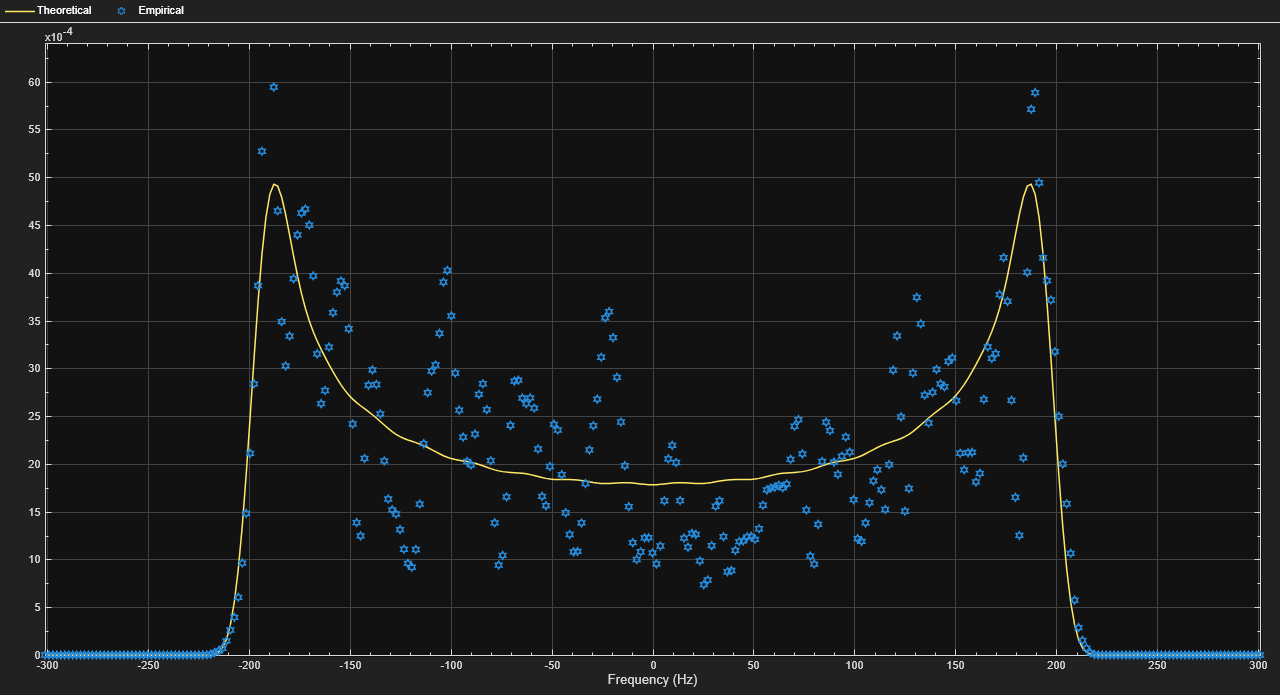
| Doppler spectrum
| Impulse and frequency responses
Select the channel visualization: Off
, Impulse
response
, Frequency response
, Doppler
spectrum
, or Impulse and frequency responses
. When
visualization is on, the selected channel characteristics, such as impulse response or
Doppler spectrum, display in a separate window. For more information, see Channel
Visualization.
Percentage of samples to display — Percentage of samples to display
25%
(default) | 10%
| 50%
| 100%
Select the percentage of samples to display: 10%
,
25%
, 50%
, or
100%
. Increasing the percentage improves display accuracy at the
expense of simulation speed.
Dependencies
This parameter appears when you set Channel
visualization to Impulse response
,
Frequency response
, or Impulse and frequency
responses
.
Path for Doppler spectrum display — Path for which Doppler spectrum is displayed
1
(default) | positive integer
Path for which the Doppler spectrum is displayed, specified as a positive integer from 1 to NP, where NP equals the value of the Discrete path delays (s) parameter.
Dependencies
This parameter appears when you set Channel
visualization to Doppler spectrum
.
Block Characteristics
Data Types |
|
Multidimensional Signals |
|
Variable-Size Signals |
|
Algorithms
The fading process for the SISO channel is described in Methodology for Simulating Multipath Fading Channels.
Cutoff Frequency Factor
The cutoff frequency factor, fc, is dependent on the type of Doppler spectrum.
For any Doppler spectrum type other than Gaussian and bi-Gaussian, fc equals 1.
For a
doppler
('Gaussian')
spectrum type, fc equalsNormalizedStandardDeviation
.For a
doppler
('BiGaussian')
spectrum type:If the
PowerGains
(1)
andNormalizedCenterFrequencies
(2)
field values are both0
, then fc equalsNormalizedStandardDeviation
(1)
.If the
PowerGains
(2)
andNormalizedCenterFrequencies
(1)
field values are both0
, then fc equalsNormalizedStandardDeviation
(2)
.If the
NormalizedCenterFrequencies
field value is[0,0]
and theNormalizedStandardDeviation
field has two identical elements, then fc equalsNormalizedStandardDeviation
(1)
.In all other cases, fc equals 1.
References
[1] Oestges, C., and B. Clerckx. MIMO Wireless Communications: From Real-World Propagation to Space-Time Code Design. Academic Press, 2007.
[2] Correira, L. M. Mobile Broadband Multimedia Networks: Techniques, Models and Tools for 4G. Academic Press, 2006.
[3] Kermoal, J. P., L. Schumacher, K. I. Pedersen, P. E. Mogensen, and F. Frederiksen. "A stochastic MIMO radio channel model with experimental validation." IEEE Journal on Selected Areas of Communications. Vol. 20, Number 6, 2002, pp. 1211–1226.
[4] Jeruchim, M., P. Balaban, and K. S. Shanmugan. Simulation of Communication Systems. Second Edition. New York: Kluwer Academic/Plenum, 2000.
[5] Pätzold, Matthias, Cheng-Xiang Wang, and Bjorn Olav Hogstand. "Two New Sum-of-Sinusoids-Based Methods for the Efficient Generation of Multiple Uncorrelated Rayleigh Fading Waveforms." IEEE Transactions on Wireless Communications. Vol. 8, Number 6, 2009, pp. 3122–3131.
Extended Capabilities
C/C++ Code Generation
Generate C and C++ code using Simulink® Coder™.
Version History
Introduced in R2017bR2022b: Updates to channel visualization display
The channel visualization feature now presents:
Configuration settings in the bottom toolbar on the plot window.
Plots side-by-side in one window when you select the
Impulse and frequency response
channel visualization option.
See Also
Blocks
Functions
Objects
Topics
MATLAB Command
You clicked a link that corresponds to this MATLAB command:
Run the command by entering it in the MATLAB Command Window. Web browsers do not support MATLAB commands.
Select a Web Site
Choose a web site to get translated content where available and see local events and offers. Based on your location, we recommend that you select: .
You can also select a web site from the following list
How to Get Best Site Performance
Select the China site (in Chinese or English) for best site performance. Other MathWorks country sites are not optimized for visits from your location.
Americas
- América Latina (Español)
- Canada (English)
- United States (English)
Europe
- Belgium (English)
- Denmark (English)
- Deutschland (Deutsch)
- España (Español)
- Finland (English)
- France (Français)
- Ireland (English)
- Italia (Italiano)
- Luxembourg (English)
- Netherlands (English)
- Norway (English)
- Österreich (Deutsch)
- Portugal (English)
- Sweden (English)
- Switzerland
- United Kingdom (English)
Asia Pacific
- Australia (English)
- India (English)
- New Zealand (English)
- 中国
- 日本Japanese (日本語)
- 한국Korean (한국어)