roadrunnerLaneInfo
Generate lane information in RoadRunner HD Map format from lane boundary points
Since R2023a
Syntax
Description
Add-On Required: This feature requires the Scenario Builder for Automated Driving Toolbox add-on.
[
additionally returns the spatial bounds of the geometric data specified by the lane boundary
points.laneInfo,geographicBoundary] = roadrunnerLaneInfo(lbPts)
[___] = roadrunnerLaneInfo(
specifies options using one or more name-value arguments, in addition to any combination of
output arguments from previous syntaxes. For example,
lbPts,Name=Value)SmoothBoundaries=true specifies to smooth and align the input lane
boundary points.
Examples
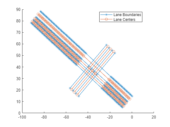
Load a MAT file containing 2D lane boundary point data into the workspace. The data includes a 2-by-1 cell array, laneBoundaryPoints, which contains the lane boundary points for two road segments, each with four lane boundaries.
load("laneBoundaryPointsJunctions.mat")
laneBoundaryPointslaneBoundaryPoints=2×1 cell array
{1×4 cell}
{1×4 cell}
Using the lane boundary points, generate lane and geographic boundary information for a RoadRunner HD Map scene model. Set the MinJunctionLength parameter to 10. This parameter value specifies that, if the distance between two road segments is greater than 10 meters, the function adds a perpendicular road between the two road segments to form a junction connecting them.
[laneInfo,geographicBoundary] = roadrunnerLaneInfo(laneBoundaryPoints, ...
    MinJunctionLength=10);
Create an empty RoadRunner HD Map by using the roadrunnerHDMap object.
rrMap = roadrunnerHDMap;
Add the generated lane and geographic boundary information to the RoadRunner HD Map object.
rrMap.Lanes = laneInfo.Lanes;
rrMap.LaneBoundaries = laneInfo.LaneBoundaries;
rrMap.GeographicBoundary = geographicBoundary;
Plot the map.
plot(rrMap)
Write the RoadRunner HD Map to a binary file, which you can import into RoadRunner.
write(rrMap,"lanes.rrhd")Specify the path to your local RoadRunner installation folder. This code shows the path for the default installation location on Windows®.
rrAppPath = "C:\Program Files\RoadRunner " + matlabRelease.Release + "\bin\win64";
To open RoadRunner using MATLAB®, specify the path to your RoadRunner project. This code shows the default path for a sample project folder location in Windows®.
rrProjectPath = "C:\RR\MyProjects";Open RoadRunner by using the roadrunner object.
rrApp = roadrunner(rrProjectPath,InstallationFolder=rrAppPath);
Copy the RoadRunner HD Map file to the RoadRunner project.
copyfile("lanes.rrhd",rrProjectPath+"\Assets")
Specify options to import RoadRunner HD Map into RoadRunner. Set your build options for the RoadRunner HD Map so that it does not create overlap groups, instead creating an automatic junction where the two roads intersect.
overlapGroupsOptions = enableOverlapGroupsOptions(IsEnabled=false);
buildOptions = roadrunnerHDMapBuildOptions(EnableOverlapGroupsOptions=overlapGroupsOptions);
importOptions = roadrunnerHDMapImportOptions(BuildOptions=buildOptions);
Import the lanes.rrhd scene file into RoadRunner.
importScene(rrApp,"lanes.rrhd","RoadRunner HD Map",importOptions)

Note: Use of the Scene Builder Tool requires a RoadRunner Scene Builder license.
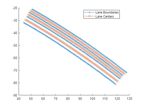
Load a MAT file containing 3D lane boundary point data into the workspace. The data includes a cell array, laneBoundaryPoints, which contains the lane boundary points for one road segment with four lane boundaries. The z-coordinates of lane boundaries represent the road elevation information.
load("laneBoundaryPoints3d.mat")
laneBoundaryPoints
laneBoundaryPoints = 1×1 cell array
{1×4 cell}
Generate lane information in RoadRunner HD Map format from lane boundary points by using the roadrunnerLaneInfo function.
[laneInfo,geographicBoundary] = roadrunnerLaneInfo(laneBoundaryPoints);
Create an empty RoadRunner HD Map by using the roadrunnerHDMap object.
rrMap = roadrunnerHDMap;
Add the generated lane and geographic boundary information to the RoadRunner HD Map object.
rrMap.Lanes = laneInfo.Lanes;
rrMap.LaneBoundaries = laneInfo.LaneBoundaries;
rrMap.GeographicBoundary = geographicBoundary;
Plot the map.
plot(rrMap)
Write the RoadRunner HD Map to a binary file, which you can import into RoadRunner.
write(rrMap,"lanes.rrhd")Specify the path to your local RoadRunner installation folder. This code shows the path for the default installation location on Windows®.
rrAppPath = "C:\Program Files\RoadRunner " + matlabRelease.Release + "\bin\win64";
To open RoadRunner using MATLAB®, specify the path to your RoadRunner project. This code shows the default path for a sample project folder location in Windows®.
rrProjectPath = "C:\RR\MyProjects";Open RoadRunner by using the roadrunner object.
rrApp = roadrunner(rrProjectPath,InstallationFolder=rrAppPath);
Copy the RoadRunner HD Map file to the RoadRunner project.
copyfile("lanes.rrhd",rrProjectPath+"\Assets")
Specify options to import RoadRunner HD Map into RoadRunner. Set your build options for the RoadRunner HD Map so that it does not create overlap groups, instead creating an automatic junction where the two roads intersect.
overlapGroupsOptions = enableOverlapGroupsOptions(IsEnabled=false);
buildOptions = roadrunnerHDMapBuildOptions(EnableOverlapGroupsOptions=overlapGroupsOptions);
importOptions = roadrunnerHDMapImportOptions(BuildOptions=buildOptions);
Import the lanes.rrhd scene file into RoadRunner.
importScene(rrApp,"lanes.rrhd","RoadRunner HD Map",importOptions)
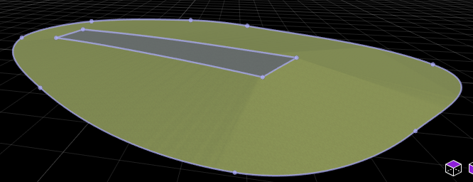
This figure shows you the scene imported into RoadRunner. A surface is modeled around the road by using the Surface Tool. For more information on how to model surfaces around roads, see Surface Tool (RoadRunner).
Note: Use of the Scene Builder Tool requires a RoadRunner Scene Builder license.
Input Arguments
Name-Value Arguments
Output Arguments
Version History
Introduced in R2023a