Label Lidar Point Clouds for Object Detection
The Ground Truth Labeler app enables you to label point cloud data obtained from lidar sensors. To label point clouds, you use cuboids, which are 3-D bounding boxes that you draw around the points in a point cloud. You can use cuboid labels to create ground truth data for training object detectors.
This example walks you through labeling lidar point cloud data by using cuboids.
Set Up Lidar Point Cloud Labeling
Load a point cloud sequence into the app and define a cuboid label.
Open the Ground Truth Labeler app. At the MATLAB® command prompt, enter this command.
groundTruthLabeler
On the app toolstrip, select Import > Add Signals.
In the Add/Remove Signal dialog box, set Source Type to
Point Cloud Sequence.In the Folder Name parameter, browse for the
lidarSequencefolder, which contains the point cloud sequence.matlabrootmatlabrootfunction.matlabroot\toolbox\driving\core\drivingdata\lidarSequenceClick Add Source to load the point cloud sequence, using the default timestamps. Then, click OK to close the Add/Remove Signal dialog box. The app displays the first point cloud in the sequence.
In the Ground Truth Labeler tab, from the toolstrip, click Add Label and select
Rectangle/Cuboid.In the Define New Rectangle Label dialog box, specify Label Name as
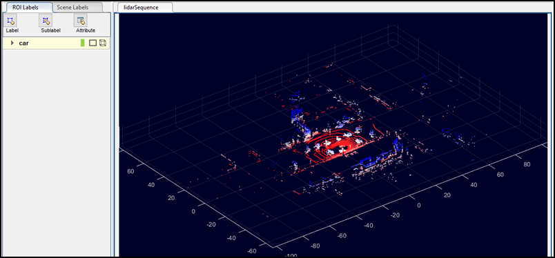
car, and click OK. The label car appears on the ROI Label Definitions pane in the left side of the app.
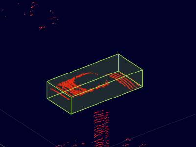
This figure shows the Ground Truth Labeler app setup after following these steps.
Zoom, Pan, and Rotate Frame
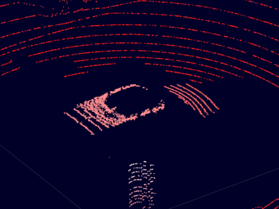
The zoom, pan, and 3-D rotation options help you locate and label objects of interest in a point cloud. Use these tools to zoom in and center on the ego vehicle in the first point cloud frame. The ego vehicle is located at the origin of the point cloud.
In the upper-right corner of the frame, click the Zoom In button
 .
.Click the ego vehicle until you are zoomed in enough to see the points that make it up.
Optionally, you can use the Pan button ![]() or Rotate 3D button
or Rotate 3D button ![]() to help you view more of the ego vehicle points. To
view additional options for viewing or rotating the point cloud, click the Rotate 3D
button and then right-click the point cloud frame. The options provided are the same
options provided with the
to help you view more of the ego vehicle points. To
view additional options for viewing or rotating the point cloud, click the Rotate 3D
button and then right-click the point cloud frame. The options provided are the same
options provided with the pcshow function.
Hide Ground
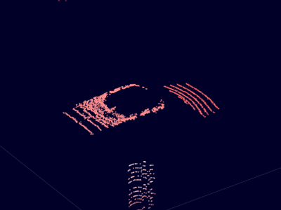
The point cloud data includes points from the ground, which can make it more difficult
to isolate the ego vehicle points. The app provides an option to hide the ground by
using the segmentGroundFromLidarData function.
Hide the ground points from the point cloud. On the app toolstrip, on the Lidar tab, click Hide Ground. This setting applies to all frames in the point cloud.
This option only hides the ground from the display. It does not remove ground data from the point cloud. If you label a section of the point cloud containing hidden ground points, when you export the ground truth labels, those ground points are a part of that label.
To configure the ground hiding algorithm, click Ground Settings and adjust the options in the Ground Settings dialog box.
Label Cuboid
Label the ego vehicle by using a cuboid label.
In the ROI Label Definitions pane on the left, click the car label.
Select the lidar point sequence frame by clicking the lidarSequence tab.
Note
To enable the labeling keyboard shortcuts, you must first select the signal frame.
Move the pointer over the ego vehicle until the blue preview cuboid encloses the ego vehicle points. The points enclosed in the preview cuboid highlight in yellow.
To resize the preview cuboid, hold the A key and move the mouse scroll wheel up or down.
Optionally, to resize the preview cuboid in only the x-, y-, or z-direction, move the scroll wheel up and down while holding the X, Y, or Z key, respectively.
Click the signal frame to draw the cuboid. Because the Shrink to Fit option is selected by default on the app toolstrip, the cuboid shrinks to fit the points within it.
For more control over the labeling of point clouds, on the app toolstrip, click
Snap to Cluster. When you label with this option selected, the
cuboid snaps to the nearest point cloud cluster by using the segmentLidarData function. To configure point cloud clustering, click
Cluster Settings and adjust the options in the dialog box. To
view point cloud clusters as you navigate between frames, select View Clusters in this dialog box. During playback of a signal, the
visualization of point cloud clusters is disabled.
Modify Cuboid Label
After drawing a cuboid label, you can resize or move the cuboid to make the label more accurate. For example, in the previous procedure, the Shrink to Fit option shrinks the cuboid label to fit the detected ego vehicle points. The actual ego vehicle is slightly larger than this cuboid. Expand the size of this cuboid until it more accurately reflects the size of the ego vehicle.
To enable the point cloud labeling keyboard shortcuts, verify that the lidarSequence tab is selected.
In the signal frame, click the drawn cuboid label. Drag the faces to expand the cuboid.
Move the cuboid until it is centered on the ego vehicle. Hold Shift and drag the faces of the cuboid.

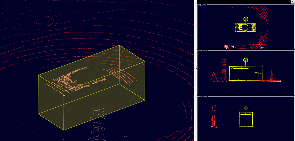
Use projected view to adjust the cuboid label in top-view, side-view and front-view simultaneously. Under Lidar tab in the toolstrip, select the Projected View option from the Camera View section, to enable this view.
Apply Cuboids to Multiple Frames
When labeling objects between frames, you can copy cuboid labels and paste them to other frames.
Select the cuboid for the ego vehicle and press Ctrl+C to copy it.
At the bottom of the app, click the Next Frame button
 to navigate to the next frame.
Press Ctrl+V to paste the cuboid onto the frame.
You can also use an automation algorithm to apply a label to multiple frames. The app provides a built-in temporal interpolation algorithm for labeling point clouds in intermediate frames. For an example that shows that how to apply this automation algorithm, see Label Ground Truth for Multiple Signals.
Configure Display
The app provides additional options for configuring the display of signal frames.
Change Colormap
For additional control over the point cloud display, on the Lidar tab, you can change the colormap options. You can also change the colormap values by changing the Colormap Value parameter, which has these options:
Z Height— Colormap values increase along the z-axis. Select this option when finding objects that are above the ground, such as traffic signs.Radial Distance— Colormap values increase away from the point cloud origin. Select this option when finding objects that are far from the origin.
Change Views
On the Lidar tab of the app toolstrip, the Camera View section contains options for changing the perspective from which you view the point cloud. These views are centered at the point cloud origin, which is the assumed position of the ego vehicle.
You can select from these views:
Bird's Eye View — View the point cloud from directly above the ego vehicle.
Chase View — View the point cloud from a few meters behind the ego vehicle.
Ego View — View the point cloud from inside the ego vehicle.
Projected View — View the point cloud with cuboid label from top-view, side-view, and front-view simultaneously.
These views assume that the vehicle is traveling along the positive x-direction of the point cloud. If the vehicle is traveling in a different direction, set the appropriate option in the Ego Direction parameter.
Use these views when verifying your point cloud labels. Avoid using these views while labeling. Instead, use the default view and locate objects to label by using the pan, zoom, and rotation options.