Zoom FFT
High-resolution FFT of a portion of a spectrum
Libraries:
DSP System Toolbox /
Transforms
Description
The Zoom FFT block computes the fast Fourier Transform (FFT) of a
signal over a portion of frequencies in the Nyquist interval. By setting an appropriate
decimation factor D, and sampling rate Fs, you can
choose the bandwidth of frequencies to analyze BW, where
BW = Fs/D. You can also
select a specific range of frequencies to analyze in the Nyquist interval by choosing
the center frequency of the desired band. If you set
Sample rate mode to Use normalized frequency
(0 to 1), the block sets BW as
2/D. (since R2024b)
The resolution of a signal is the ratio of Fs and the FFT length (L). Using zoom FFT, you can retain the same resolution you would achieve with a full-size FFT on your original signal by computing a small FFT on a shorter signal. The shorter signal comes from decimating the original signal. The savings come from being able to compute a much shorter FFT while achieving the same resolution. For a decimation factor of D, the new sampling rate, Fsd, is Fs/D, and the new frame size (and FFT length) is Ld = L/D. The resolution of the decimated signal is Fsd/Ld = Fs/L. To achieve a higher resolution of the shorter band, use the original FFT length, L, instead of the decimated FFT length, Ld.
Examples
Ports
Input
Output Arguments
Parameters
Block Characteristics
Data Types |
|
Multidimensional Signals |
|
Variable-Size Signals |
|
Algorithms
The zoom FFT algorithm leverages bandpass filtering before computing the FFT of the signal. The concept of bandpass filtering is that suppose you are interested in the band [F1, F2] of the original input signal, sampled at the rate Fs Hz. If you pass this signal through a complex (one-sided) bandpass filter centered at Fc = (F1+F2)/2, with the bandwidth BW = F2 – F1, and then downsample the signal by a factor of D = floor(Fs/BW), the desired band comes down to the baseband.


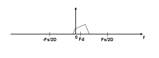
If Fc cannot be expressed in the form of k×Fs/D, where k is an integer, then the shifted, decimated spectrum is not centered at DC. In this case, the center frequency gets translated to Fd.
The complex bandpass filter is obtained by first designing a lowpass filter prototype and then multiplying the lowpass coefficients with a complex exponential. This algorithm uses a multirate, multistage FIR filter as the lowpass filter prototype. To obtain the bandpass filter, the coefficients of each stage are frequency shifted. The decimation factor is the cumulative decimation factor of each stage. The complex bandpass filter followed by the decimator are implemented using an efficient polyphase structure. For more details on the design of the complex bandpass filter from the multirate multistage FIR filter prototype, see Zoom FFT and Complex Bandpass Filter Design.
References
[1] Harris, F.J. Multirate Signal Processing for Communication Systems. Prentice Hall, 2004, pp. 208–209.
Extended Capabilities
Version History
Introduced in R2017bSee Also
Objects
dsp.ZoomFFT|dsp.FFT|dsphdl.FFT(DSP HDL Toolbox) |dsp.IFFT|dsphdl.IFFT(DSP HDL Toolbox)
Blocks
- FFT | FFT (DSP HDL Toolbox) | Magnitude FFT | Short-Time FFT
