Complex Bandpass Filter Design
This example shows how to design complex bandpass filters. Complex bandpass filters are used in many applications from IF subsampling digital down converters to vestigial sideband modulation schemes for analog and digital television broadcast. One easy way to design a complex bandpass filter is to start with a lowpass prototype and apply a complex shift frequency transformation. This example reviews lowpass prototypes from single-stage single-rate FIR filters to multistage multirate FIR filters to IIR filters.
Frequency Shift of a Lowpass FIR Design
To apply a complex frequency shift to a lowpass FIR design, multiply the filter coefficients by (also known as heterodyne with) a complex exponential.
function modNum = modulateFIR(Num,Fc)
    N = length(Num)-1;
    modNum = Num.*exp(1j*Fc*pi*(0:N));
end
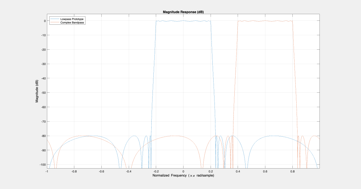
For example, transform a lowpass filter prototype by a normalized frequency of 0.6.
% Lowpass prototype
Hlp = designfilt('lowpassfir',PassbandFrequency=0.0938,StopbandFrequency=0.1562,StopbandAttenuation=80, ...
                                DesignMethod='kaiserwin',MinOrder="even",SystemObject=true);

Fc = .6;   % Desired frequency shift
Hbp = clone(Hlp);
Hbp.Numerator = modulateFIR(Hbp.Numerator,Fc);

FA = filterAnalyzer(Hlp,Hbp,FrequencyRange='centered',...
                        LegendStrings=["Lowpass Prototype","Complex Bandpass"]);
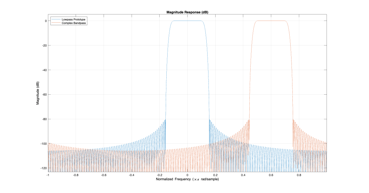
Examine the zeros of the prototype filter versus the transformed filter. The frequency shift rotates the zeros of the lowpass prototype by a normalized frequency of 0.6.
newDisplayNum = duplicateDisplays(FA);
setAnalysisOptions(FA,DisplayNums=newDisplayNum,Analysis='polezero');
setAnalysisOptions(FA,Analysis='polezero');
You can apply the same technique to single-stage multirate filters as well.
Multistage Multirate FIR Design
In multistage multirate FIR filters, the coefficients of each stage are multiplied with a complex exponential. You need to account for the different relative frequencies that each stage operates in. Consider for example a multistage decimator of order 16. You can design such a decimator using the designRateConverter function. This particular design has 4 stages - each stage is a decimator which downsamples by a factor of 2.
Hd = designRateConverter(DecimationFactor=16,OutputSampleRate=1,Bandwidth=0.45,StopbandAttenuation=75,Verbose=true)
designRateConverter(InterpolationFactor=1, DecimationFactor=16, OutputSampleRate=1, Bandwidth=0.45, StopbandAttenuation=75, MaxStages=Inf, CostMethod="estimate", OptimizeFor="MPIS", Tolerance=0, ToleranceUnits="absolute")

Conversion ratio: 1:16
Input sample rate: 16
Output sample rate: 1
Hd =
  dsp.FilterCascade with properties:

         Stage1: [1×1 dsp.FIRDecimator]
         Stage2: [1×1 dsp.FIRDecimator]
         Stage3: [1×1 dsp.FIRDecimator]
         Stage4: [1×1 dsp.FIRDecimator]
    CloneStages: true
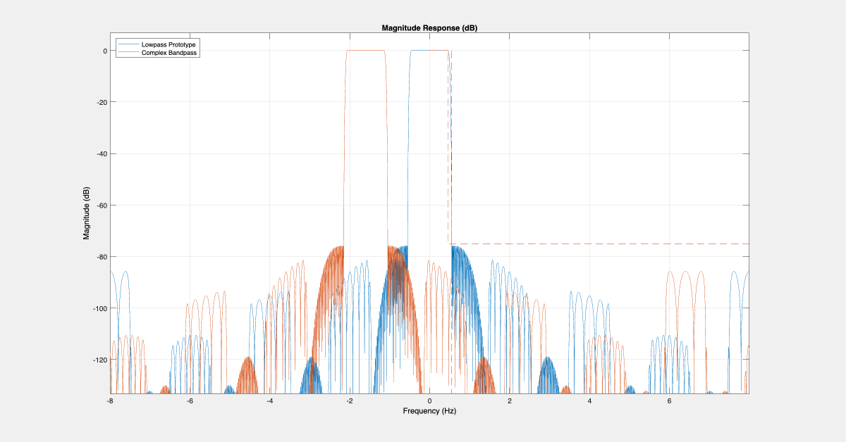
In a multistage decimator, the desired frequency shift applies only to the first stage. Subsequent stages must also scale the desired frequency shift by their respective cumulative decimation factor.
Fc  = -.2;  % Desired frequency shift
Hdbp = clone(Hd);

Fck = Fc;
for k = 1:Hdbp.getNumStages
    Stagek = Hdbp.(sprintf('Stage%i',k));
    Stagek.Numerator = modulateFIR(Stagek.Numerator, Fck);
    % Update the frequency shift applied to the k-th stage
    Fck = Fck*Stagek.DecimationFactor;
end

filterAnalyzer(Hd,Hdbp,FrequencyRange='centered'); pause(1)
setLegendStrings(FA,["Multistage Lowpass Prototype Decimator","Multistage Complex Bandpass Decimator"]);
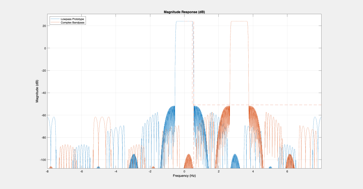
Similarly, in a multistage interpolator, the desired frequency shift applies only to the last stage. Previous stages must also scale the desired frequency shift by their respective cumulative interpolation factor.
Hi = designRateConverter(InterpolationFactor=16,InputSampleRate=1,Bandwidth=0.45,StopbandAttenuation=75);

Fc = .4;   % Desired frequency shift
Hibp = clone(Hi);

Fck = Fc;
for k = Hibp.getNumStages:-1:1
    Stagek = Hibp.(sprintf('Stage%i',k));
    Stagek.Numerator = modulateFIR(Stagek.Numerator, Fck);
    % Update the frequency shift applied to the k-th stage
    Fck = Fck*Stagek.InterpolationFactor;
end

filterAnalyzer(Hi,Hibp,FrequencyRange='centered');
setLegendStrings(FA,["Multistage Lowpass Prototype Interpolator","Multistage Complex Bandpass Interpolator"])
You can design multistage bandpass filters easily by using the dsp.ComplexBandpassDecimator System object™. The object designs the bandpass filter based on the specified decimation factor, center frequency, and sample rate. There is no need to translate lowpass coefficients to bandpass as in the filters you designed in the previous steps. The object does this for you.
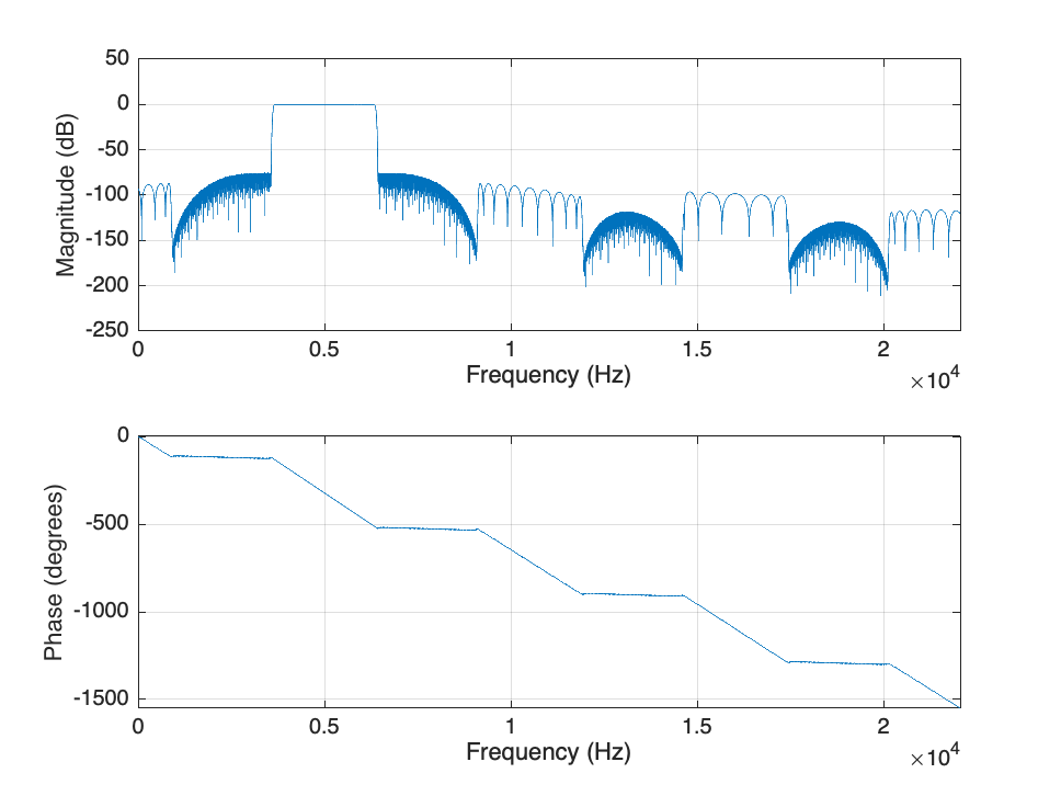
Design a complex bandpass filter with a decimation factor of 16, a center frequency of 5 KHz, a sampling rate of 44.1 KHz, a transition width of 100 Hz, and a stopband attenuation of 75 dB using the System object.
bp = dsp.ComplexBandpassDecimator(16,5000,SampleRate=44100,...
                                  TransitionWidth=100,...
                                  StopbandAttenuation=75);
Visualize the filter response using the freqz function.
freqz(bp)
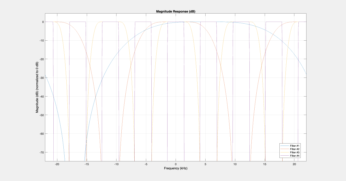
Visualize the response of the different filter stages using the visualize function.
visualize(bp);
Only the first filter is shifted to 5 KHz. The subsequent filter stages are lowpass and have real coefficients. Set the MinimizeComplexCoefficients property to false to shift all filter stages to 5000 KHz.
Use the cost function to calculate the cost of the bandpass filter.
cost(bp)
ans = struct with fields:
                      NumCoefficients: 144
                            NumStates: 272
    RealMultiplicationsPerInputSample: 27.8750
          RealAdditionsPerInputSample: 27
Single-Rate IIR Design
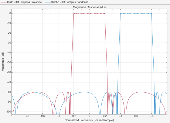
In single-rate IIR designs, you can either use a complex frequency shift transformation or a lowpass to complex bandpass IIR transformation. In the latter case, you can also modify the bandwidth of the bandpass filter.
Fp = .2;
Fs = .25;

% Design a lowpass prototype, and obtain the second order coefficients
Hiirlp = designfilt('lowpassiir',...
                    PassbandFrequency=Fp, StopbandFrequency=Fs,...
                    PassbandRipple=0.5, StopbandAttenuation=80, ...
                    DesignMethod='ellip', SystemObject=true);
B = (Hiirlp.ScaleValues(1:end-1)').*Hiirlp.Numerator;
A = Hiirlp.Denominator;

% Perform lowpass to complex bandpass transform
Fc = .6;  % Desired frequency shift

[Bc,Ac] = iirlp2bpc(B,A, ...            % Transform lowpass to complex bandpass
                    Fp,[Fc-Fp, Fc+Fp]); % Lowpass passband frequency mapped
                                        % to bandpass passband frequencies

% Construct a filter object and plot the responses
Hiircbp = dsp.SOSFilter(Bc, Ac);

filterAnalyzer(Hiirlp,Hiircbp,FrequencyRange='centered',...
                    LegendStrings=["IIR Lowpass Prototype","IIR Complex Bandpass"]);
See Also
designMultistageDecimator | designMultistageInterpolator | dsp.ComplexBandpassDecimator | dsp.FIRFilter | dsp.SOSFilter | iirlp2bpc | cost | visualize | freqz