Define Multiple AXI Master Interfaces in Reference Designs to Access DUT AXI4 Subordinate Interface
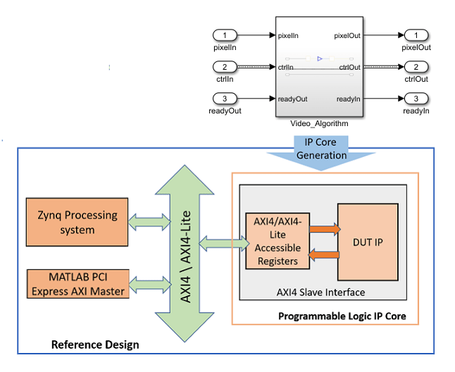
You can define multiple AXI Master interfaces in your custom reference design and access the AXI4 subordinate interfaces in the generated HDL DUT IP core for the DUT. This capability enables you to simultaneously connect the HDL DUT IP core to two or more AXI Master IP in the reference design, such as the HDL Verifier™ JTAG AXI Manager IP and the ARM® processor in the Zynq® processing system.
Vivado-Based Reference Designs
To define multiple AXI Master interfaces, you specify
the BaseAddressSpace and
MasterAddressSpace for each AXI
Master instance. Depending on your design, you may also
need to specify the IDWidth property. For more information on
ID width, see IDWidth.
This code is the syntax for the
MasterAddressSpace field when
specifying multiple AXI Master interfaces in Vivado®-based reference
designs:
'MasterAddressSpace', ...
   {'AXI Master Instance Name1/Address Space of Instance Name1', ...
    'AXI Master Instance Name2/Address_Space of Instance Name2',...};
For example, this code illustrates how you can modify the
plugin_rd file to define two AXI
Master interfaces.
% ...

%% Add custom design files
% add custom Vivado design
hRD.addCustomVivadoDesign( ...
    'CustomBlockDesignTcl', 'system_top.tcl', ...
    'VivadoBoardPart',      'xilinx.com:zc706:part0:1.0');


% ...
% ...

% The DUT IP core in this reference design is connected
% to both Zynq Processing System and the AXI Manager IP.

hRD.addRegisterInterface( ...
    'InterfaceConnection', 'axi_interconnect_0/M00_AXI', ...
    'BaseAddress',         {'0x40010000', '0x40010000'}, ...
    'MasterAddressSpace',  {'processing_system7_0/Data', 'hdlverifier_axi_manager_0/axi4m'}, ...
    );

% ...
In this example, the two AXI Master IP are the
HDL Verifier AXI Manager IP and the ARM processor. Based on the syntax of the
MasterAddressSpace, for the
HDL Verifier AXI Manager IP, the AXI Master
Instance Name is hdlverifier_axi_manager_0 and the
Address_Space of Instance Name is
axi4m.
The AXI4 subordinate interfaces in the HDL DUT IP core connect to the Xilinx® AXI Interconnect IP that is defined by the
InterfaceConnection property of the
addRegisterInterface method. The AXI4 subordinate interfaces
have a BaseAddress. This BaseAddress must map
to the MasterAddressSpace for the two
AXI Master IP, which is specified as a cell array of
character vectors.
You must make sure that the AXI Master IPs have
already been included in the Vivado reference design project. system_top.tcl is the TCL
file that is defined by the CustomBlockDesignTcl property of
the addCustomVivadoDesign method. In
this TCL file, you must make sure that the two AXI
Master IP are connected to the same Xilinx AXI Interconnect IP. The interconnects then connect the AXI
Master IPs to the AXI4 subordinate interfaces in the HDL
IP core.
After you run the IP Core Generation workflow and create the
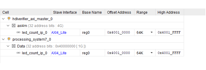
Vivado project, open the project. In the Vivado project, if you open the block design, you see the two AXI
Master IP connected to the HDL DUT IP core. If you
select the Address Editor tab, you see the AXI
Master instance names and the corresponding address
spaces.
Qsys-Based Reference Designs
To define multiple AXI Master interfaces, you specify
the BaseAddressSpace and
MasterAddressSpace for each AXI
Master instance. Depending on your design, you may also
need to specify the IDWidth property. For more information on
ID width, see IDWidth.
This code is the syntax for the InterfaceConnection field when
specifying multiple AXI Master interfaces in
Qsys™-based reference
designs:
'InterfaceConnection', ...
   {'AXI Master Instance Name1/Port name of Instance Name1', ...
    'AXI Master Instance Name2/Port name of Instance Name1', ...};
For example, this code illustrates how you can modify the
plugin_rd file to define three AXI
Master
interfaces.
% ...

%% Add custom design files
% add custom Qsys design
hRD.addCustomQsysDesign('CustomQsysPrjFile', 'system_soc.qsys');
hRD.CustomConstraints = {'system_soc.sdc','system_setup.tcl'};


% ...

% add register interfaces
hRD.addRegisterInterface( ...
    'InterfaceConnection', {'hps_0.h2f_axi_master','master_0.master','AXI_Manager_0.axm_m0'}, ...
    'BaseAddress',         {'0x0000_0000','0x0000_0000','0x0000_0000'},...
    'InterfaceType',       'AXI4');

% ...
Based on the syntax of the InterfaceConnection option, for the
HDL Verifier AXI Manager IP, the AXI Master
Instance Name is AXI_Manager_0 and the
Port name is axm_m0. For each AXI
Master IP, the BaseAddress of the
HDL IP core and InterfaceConnection must be specified as a cell
array of character vectors.
You must make sure that the AXI Master IPs have
already been included in the Qsys reference design project.
system_soc.qsys is the file that is defined by the
CustomQsysPrjFile property of the addCustomQsysDesign method. In this
file, you must make sure that the two AXI Master IP are
connected to the same Qsys AXI Interconnect IP.
The interconnects then connect the AXI Master IPs to the register interfaces in the HDL IP core.
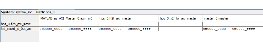
After you run the IP Core Generation workflow and create the
Quartus® project, open the project. In the Quartus project, you see the three AXI Master IP
and the AXI Master interfaces connected to the HDL IP
core for the DUT. If you select the Address Map tab, you see
the AXI Master instance names, the port names, and the
corresponding address spaces.
See Also
hdlcoder.Board | hdlcoder.ReferenceDesign