Validate HDL Implementation Model to Simscape Algorithm
If you design your algorithm by using Simscape™ switched linear blocks, you can run the Simscape HDL Workflow Advisor to generate an HDL implementation model. The HDL implementation model represents the Simscape algorithm by using Simulink® blocks that are compatible for HDL code generation.
Before you prototype the implementation model on an FPGA or target Speedgoat® FPGA I/O modules, you can verify the functionality of your design in the Simulink modeling environment. To verify the functionality, specify insertion of validation logic in the HDL implementation model when you run the Simscape HDL Workflow Advisor. This logic verifies whether the numeric results of the HDL implementation model match the original Simscape algorithm.
In some cases, there can be a mismatch in simulation results between the Simscape algorithm and the corresponding HDL implementation. Such mismatches generate warnings or assertions when you simulate the implementation model. To resolve the warnings, use a combination of various settings in the Generate implementation model task as illustrated below.
Bridge Rectifier Model
This example uses the bridge rectifier model to illustrate how to generate an implementation model with validation logic inserted in the model, and how you can resolve any assertions that may be generated when you simulate the implementation model.
Open the bridge rectifier model. In the MATLAB® Command Window, enter:
openExample('plantdeployment/BridgeRectifierModelExample',...
'supportingFile','sschdlexBridgeRectifierExample')
open_system('sschdlexBridgeRectifierExample/Simscape_system')
Inside the
Simscape_system, you see four diodes arranged in a bridge configuration. For both positive and negative input values, this configuration provides a positive, rectified output.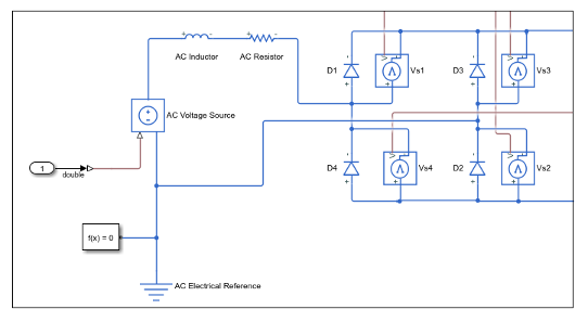
Open the Simscape HDL Workflow Advisor for your model:
openExample('plantdeployment/BridgeRectifierModelExample',...
'supportingFile','sschdlexBridgeRectifierExample')
sschdladvisor('sschdlexBridgeRectifierExample')
Right-click the State-space conversion task and select Run to Selected Task.
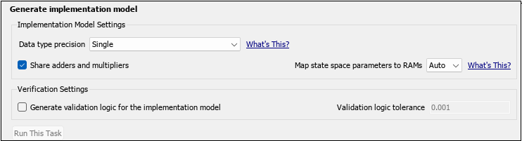
In the Generate implementation model task, select the Generate validation logic for the implementation model check box. Leave the other options with their default values and select Run This Task.
After running this task, keep the UI window for this task open. If simulating the HDL implementation model generates warnings, you modify the settings in the Generate implementation model task and then rerun this task. You do not have to modify or rerun other tasks.
Click the link to open the HDL implementation model. You see a
ValidationSubsystem that compares the simulation results of the Simscape model to the HDL implementation model. Simulate the implementation model.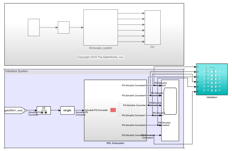
You see that simulating the model generates multiple assertions indicating a mismatch in the simulation results. If you open the Diagnostic Viewer, you see this message:
Assertion detected in
          'gmStateSpaceHDL_BridgeRectifier_HDL_SimMismatch/Validation/Check Static Range1' at time
          0.04186 [4982 similar]
The message indicates that the Simscape algorithm does not match the equivalent HDL implementation. To resolve the validation mismatch, you can modify various settings in the Generate implementation model task until the HDL implementation model matches the Simscape algorithm. In most cases, to resolve the numeric mismatch, you may want to use a combination of these settings. For more information about validation errors, see Troubleshoot Validation Errors in Simscape Hardware-in-the-Loop Workflow.
Increase Validation Logic Tolerance
Conversion of a Simscape algorithm to an equivalent HDL implementation leads to rounding errors. The default tolerance value is relatively small and can be difficult to achieve especially with single-precision data types in the HDL implementation model. To resolve the mismatch:
Start by increasing the Validation logic tolerance to an initial value such as
1e-4.Select Generate validation logic for the implementation model and run the task to generate the HDL implementation model that includes validation logic.
Simulate the model and check whether the simulation displays assertions in the Diagnostic Viewer. If the simulation results produce warnings, proceed to the next step to increase the number of solver iterations.
Increase Number of Solver Iterations
For each mode in the physical system, the switched linear workflow arrives at a state-space representation. The solver method is iterative and performs multiple computations to determine the correct mode for the next time step. After a certain number of iterations, the output value from the next time step becomes the same as the value from the previous time step. This consistency in the output value indicates the correct number of solver iterations.
The Advisor by default chooses an optimal value for the number of solver iterations. See Using Number of Solver Iterations. If increasing the tolerance value does not improve accuracy of the HDL implementation model, you can resolve the numeric mismatch by increasing the number of solver iterations.
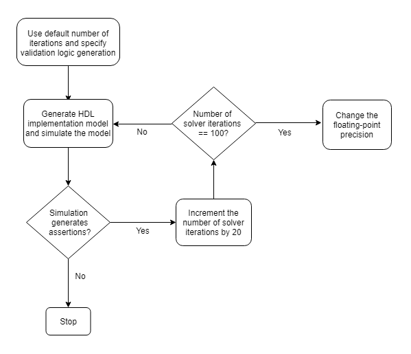
When you increase the number of solver iterations, the code generator changes the sample time of the generated HDL implementation model. A large number of iterations can increase the simulation time significantly. See Reducing Number of Solver Iterations. This flow chart illustrates how to change the Number of solver iterations.
Use Floating-Point Precision
You can use the Data type precision setting in the
Generate implementation model task to specify the floating-point data
type you want to use for the algorithm inside the HDL Subsystem. Specify
whether you want to store the matrix coefficients in single or
double data types and whether to use single or
double when performing the computations.
| Data type precision | Description |
|---|---|
Double | Using double floating-point precision increases the
numerical accuracy of the generated model and the maximum achievable target
frequency. However, the area consumption and pipeline latency are also
increased. |
Single | This is the default setting for data type precision. |
Single coefficient, double computation | This mode offers a tradeoff between Single and
Double modes of floating-point precision. To save memory
usage, the coefficients that are stored in single. The matrix
computations are then performed in double for improved
accuracy. |
This flow chart illustrates how to change the floating-point precision and improve the numeric accuracy of the generated HDL implementation model.
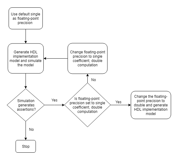
Note
Double-precision operations have large latencies and require a large
Oversampling factor to allocate sufficient delays for the
floating-point operations, which reduces the sampling frequency. For a tradeoff between
accuracy and precision, use Single coefficient, double computation as
the Data type precision.
After specifying double data types, if the simulation results still produce warnings:
Proceed to the first step to further increase the validation logic tolerance. Use a tolerance value of
1e-03and then simulate the model to see if the numeric accuracy requirements are met.Increase the number of solver iterations if you still see warnings in the Diagnostic Viewer. Continue iterating between these steps till the HDL implementation model numerically matches the Simscape algorithm.
For the bridge rectifier model, to resolve the warnings, set the Validation
logic tolerance to 1e-4 and specify the Data type
precision as double. After you generate the implementation
model with the validation logic, you see that simulating the model does not display warnings
in the Diagnostic Viewer.
Use Fixed-Point Precision
To specify fixed-point data types for the algorithm inside the HDL
Subsystem, use the Data type precision setting in the
Generate implementation model task. Specify that you want to store
the matrix coefficients in fixed-point data types when performing the
computations for the generated HDL implementation model.
| Data type precision | Description |
|---|---|
Fixed-point | This mode of data type precision determines the dynamic range of state-space matrices, and computes the appropriate fraction lengths and full-precision integer rounding modes by using the specified word length. This reduces resource utilization and improves FPGA sampling frequency by reducing the oversampling factor. |
This flow chart illustrates how to change the fixed-point precision, and improve numerical accuracy and FPGA sampling frequency while limiting the resource consumption on the hardware.
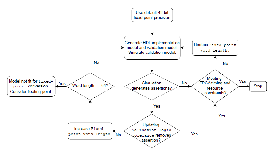
When performing fixed-point computations:
Use the default word length of 48 bits. If the simulation of validation model produces assertions, then increase the Validation logic tolerance. Update the tolerance value and simulate the model to see if the numeric accuracy requirements are met. If not, then increase the Fixed-point word length.
If the simulation results do not produce any assertions, check the FPGA sampling frequency and resource utilization. If the values are optimal, the Simscape model is expected to produce better results with
fixed-pointdata type precision else reduce the word length and simulate the validation model.
Note
Fixed-point precision operations allow a maximum fixed-point word
length of 64 bits. With this word length, if the validation model simulates without
assertions but the FPGA timing and resource constraints are not met (for example, resource
utilization is high and FPGA sampling frequency is low), then consider using a
floating-point data type precision instead.