cosimulationConfiguration
Description
The cosimulationConfiguration object controls the creation of an
HDL Cosimulation block or System object™ for a specified HDL module.
Creation
Syntax
Description
cosimObj = cosimulationConfiguration(HDLSimulator,SubWorkflow,HDLTopLevelName)cosimulationConfiguration object with the specified
HDLSimulator, SubWorkflow, and
HDLTopLevelName values.
This workflow is a command-line alternative to using the Cosimulation Wizard for creating an HDL
Cosimulation block or an hdlverifier.HDLCosimulation
System object.
cosimObj = cosimulationConfiguration(MATfile)cosimulationConfiguration object based on the results of a
previous run of the Cosimulation Wizard or command-line
workflows.
Properties
Object Functions
portInterface | Display port specifications |
runWorkflow | Execute cosimulation workflow and generate required artifacts |
specifyClock | Assign clock ports to cosimulation block or System object |
specifyInput | Assign HDL input ports to cosimulation block or System object |
specifyOutput | Assign HDL output ports to cosimulation block or System object |
specifyReset | Assign reset ports to cosimulation block or System object |
specifyUnused | Label HDL ports as unused ports |
Examples
This example shows how to cosimulate a raised cosine filter in Simulink® using the command-line interface. It follows the same workflow to generate cosimulation artifacts as in Get Started with Simulink HDL Cosimulation, but it uses the command line instead of the Cosimulation Wizard.
Configure Cosimulation Workflow
Create a cosimulation configuration object.
c = cosimulationConfiguration('ModelSim','Simulink','rcosflt_rtl');
Set up the HDL file.
c.HDLFiles = {'./rcosflt_rtl.v','Verilog'};
Set the filter_out port as an output with a signed fixed-point data-type, and set the fraction length to 29.
specifyOutput(c,'filter_out',Datatype='Fixedpoint',Signed=true,FractionLength=29)
Set the clock to a period of 20 ns, and set the reset duration to 15 ns.
specifyClock(c,'clk',Period=20)
specifyReset(c,'reset',Duration=15)
Display the port table. It reflects the settings just made for output, clock, and reset attributes. The other design ports will take on default attributes.
portInterface(c);
----- Input Data Ports -----
  0×1 empty table

    Name
    ____


----- Output Data Ports -----
  2×5 table

                Name                 SampleTime       DataType       Signed    FractionLength
    _____________________________    __________    ______________    ______    ______________

    {'default_output_definition'}        1         {'Inherit'   }    false            0
    {'filter_out'               }        1         {'Fixedpoint'}    true            29


----- Clock Ports -----
  2×3 table

                Name                   Edge       Period
    ____________________________    __________    ______

    {'default_clock_definition'}    {'Rising'}      10
    {'clk'                     }    {'Rising'}      20


----- Reset Ports -----
  2×3 table

                Name                InitialValue    Duration
    ____________________________    ____________    ________

    {'default_reset_definition'}         1              8
    {'reset'                   }         1             15


----- Unused Ports -----
  0×1 empty table

    Name
    ____
Generate HDL Cosimulation Block
Run the workflow to generate an HDL Cosimulation block and the accompanying files.
runWorkflow(c);
-------------------- Step 1------------------
Select the type of cosimulation you want to do.If the HDL simulator executable you want to use is not on the system path in your environment you must specify its location.
-------------------- Step 2------------------
Add all VHDL, Verilog, and/or script files to be used in cosimulation to the following table. If the file type cannot be automatically detected or the detection result is incorrect, specify the correct file type in the table. If possible, we will determine the compilation order automatically using HDL simulator provided functionality. Then the HDL files can be added in any order.
-------------------- Step 3------------------
HDL Verifier has automatically generated the following HDL compilation commands. You can customize these commands with optional parameters as specified in the HDL simulator documentation but they are sufficient as shown to compile your HDL code for cosimulation. The HDL files will be compiled when you click Next.
Compiling HDL design. Please wait ...
###Compiling HDL design
Reading pref.tcl

# 2024.2

# do hdlverifier_compile_design.do
# ** Warning: (vlib-34) Library already exists at "work".
# Errors: 0, Warnings: 1
# Loading project compile_project
# .
# QuestaSim-64 vlog 2024.2 Compiler 2024.05 May 20 2024
# Start time: 14:09:05 on Aug 29,2025
# vlog -work work -vopt C:/Users/user/OneDrive - MathWorks/Documents/MATLAB/ExampleManager/user.Bdoc25b.j2987061/hdlverifier-ex80882452/rcosflt_rtl.v
# -- Compiling module rcosflt_rtl
#
# Top level modules:
# 	rcosflt_rtl
# End time: 14:09:07 on Aug 29,2025, Elapsed time: 0:00:02
# Errors: 0, Warnings: 0
# Compile of rcosflt_rtl.v was successful.
# All compile dependencies have been resolved.vlog -work work -vopt -stats=none {C:/Users/user/OneDrive - MathWorks/Documents/MATLAB/ExampleManager/user.Bdoc25b.j2987061/hdlverifier-ex80882452/rcosflt_rtl.v}
# reading E:/share/apps/HDLTools/ModelSim/questasim-2024.2/Windows/win64/../modelsim.ini
# QuestaSim-64 vlog 2024.2 Compiler 2024.05 May 20 2024
# -- Compiling module rcosflt_rtl
#
# Top level modules:
# 	rcosflt_rtl
...done
-------------------- Step 4------------------
Use 'Shared Memory' communication method if your firewall policy does not allow TCP/IP socket communication.
Elaborating and Loading HDL simulation image. Please wait ...
Waiting for HDL Simulator to startup ...
120 seconds to time-out ...
To stop this process, press Ctrl+C in MATLAB console.
Waiting for HDL Simulator to startup ...
119 seconds to time-out ...
To stop this process, press Ctrl+C in MATLAB console.
Waiting for HDL Simulator to startup ...
118 seconds to time-out ...
To stop this process, press Ctrl+C in MATLAB console.
Waiting for HDL Simulator to startup ...
117 seconds to time-out ...
To stop this process, press Ctrl+C in MATLAB console.
Waiting for HDL Simulator to startup ...
116 seconds to time-out ...
To stop this process, press Ctrl+C in MATLAB console.
Waiting for HDL Simulator to startup ...
115 seconds to time-out ...
To stop this process, press Ctrl+C in MATLAB console.
Waiting for HDL Simulator to startup ...
114 seconds to time-out ...
To stop this process, press Ctrl+C in MATLAB console.
Waiting for HDL Simulator to startup ...
113 seconds to time-out ...
To stop this process, press Ctrl+C in MATLAB console.
Waiting for HDL Simulator to startup ...
112 seconds to time-out ...
To stop this process, press Ctrl+C in MATLAB console.
...done
-------------------- Step 5------------------
Specify all input and output port types. Input signals that are identified as 'Clock' and 'Reset' signals will be forced in the HDL simulator through Tcl commands. You can specify the timing parameters for forced 'Clock' and 'Reset' signals in the next step. If you want to drive your HDL clock and reset signals with Simulink signals, mark them as 'Input'.
-------------------- Step 6------------------
Set the sample time and data type for each output port. You can specify the sample time as -1, which means that it will be inherited via back propagation in the Simulink model. Back propagation may fail in certain circumstances; click Help for details.
-------------------- Step 7------------------
Set clock and reset parameters here. The time in these tables refers to time in the HDL simulator.
Please wait while generating waveforms.
...done
-------------------- Step 8------------------
The diagram below shows the current settings for forced 'Clock' and 'Reset' signals. The red line represents the time in the HDL simulation at which MATLAB/Simulink will start (i.e. cosimulation will start).

To change the MATLAB/Simulink start time relative to the HDL simulation time, enter the new start time below. To avoid a race condition, make sure the start time does not coincide with the active edge of any clock signal. You can do so by moving the start time or by changing the clock active edge in the previous step (click Back).
-------------------- Step 9------------------
When you click Finish, the Cosimulation Wizard performs the following actions:
 - Creates and opens a new Simulink model containing an HDL Cosimulation block configured to your specifications.
 - Generates the scripts to compile your HDL code and launch the HDL simulator according
 to the choices you made with this assistant.
 - (If you check the box below) Configures the HDL Cosimulation block to assist you in setting the timescale
 when you cosimulate the block for the first time.
 - (If you uncheck the box below) The timescale is set to the default setting of 1 Simulink second = 1 second in the HDL simulator
 or you may change it below.
Generating blocks ... Please wait.
Warning: The model name 'hdlverifier_wizard_rcosflt_rtl' is shadowing another
name in the MATLAB workspace or path. Type "which -all
hdlverifier_wizard_rcosflt_rtl" at the command line to find the other uses of
this name. You should change the name of the model to avoid problems.
...done
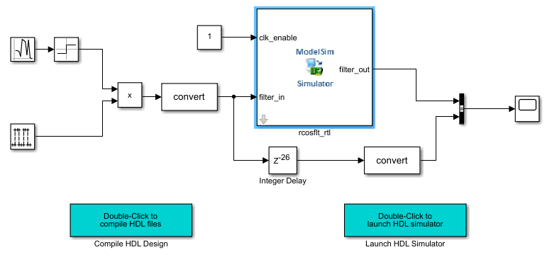
The workflow executes the steps and generates a Simulink model named hdlverifier_wizard_rcosflt_rtl.slx, which includes an HDL Cosimulation block and two additional blocks for compilation and communication with the HDL simulator.
Open the provided testbench model.
open_system('rcosflt_tb.slx')
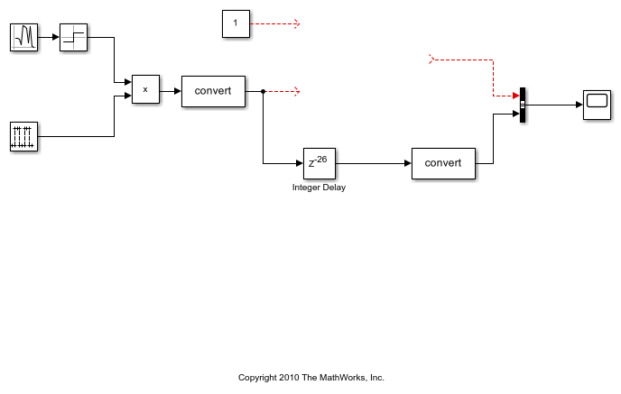
Drag the generated HDL Cosimulation block to the canvas, and connect its inputs and outputs to the testbench. Your model now looks similar to the following figure.
Run Cosimulation and Verify HDL Design
Start the HDL simulator by double-clicking the block labeled Launch HDL Simulator.
When the HDL simulator is ready, return to Simulink and start the simulation.
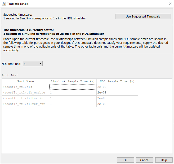
Determine timescale. Since the
AutoTimeScaleproperty is set to automatically determine the timescale at start of simulation, HDL Verifier launches the Timescale Details graphical interface instead of starting the simulation. Both the HDL simulator and Simulink sample thefilter_inandfilter_outports at 1 second. However, their sample time in the HDL simulator should be the same as the clock period (20 ns). Change the Simulink sample time of/rcosflt_rtl/clkto 1 (seconds), and press Enter. The wizard then updates the table. The following figure shows the new timescale: 1 second in Simulink corresponds to 2e-008 s in the HDL simulator.
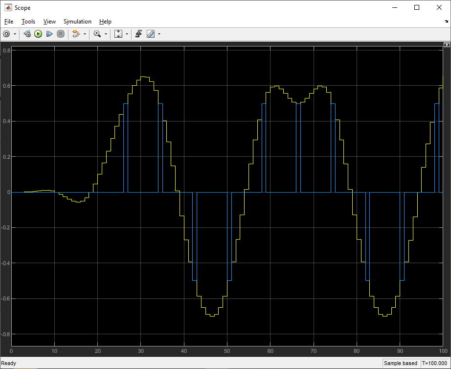
4. Click OK to close the Timescale Details dialog box. Restart the Simulink simulation and verify the results from the scope in the testbench model.
The scope displays both the delayed version of input to the raised cosine filter and that filter's output. If you sample the output of this filter directly, no inter-symbol-interference occurs.
Limitations
The
.matfile that you generate in a MATLAB release is not guaranteed to work in other releases. For different MATLAB releases, regenerate the.matfile by running the Cosimulation Wizard workflow to completion using any customizations required for your design.