Analyze Optical Coatings Using Optical System Designer
R2026bThis example shows how to design and apply anti-reflective optical coatings to an optical system by using the Optical System Designer app. Each uncoated glass surface reflects approximately 4% of incident light due to the refractive index difference between the lens element material and the surrounding medium. A simple three-element system like a Cooke Triplet, containing six air-glass interfaces, transmits only about 78% of incident light. In multi-element systems with more surfaces, these cumulative reflection losses become severe, significantly degrading image quality. By applying thin-film anti-reflective coatings, you can minimize these surface reflections and improve overall system transmittance.
In this example, you:
Design a seven-layer broadband anti-reflective (BBAR) coating by using the
opticalCoatingEditorand add the coating to thecoatingLibraryLoad a double Gauss system in the Optical System Designer app and apply the coating to all lens surfaces
Observe the improvement in system transmission from approximately 42% to 90%
To learn how to design an optical system by using the app, see Design Optical System Using Optical System Designer. For information on other analysis types available in the app, see Analyze Optical System Using Optical System Designer.
Design Broadband Anti-Reflective Coating
To reduce surface reflections across a wide range of wavelengths, design a BBAR coating by using the optical coating editor. Launch the optical coating editor by using the opticalCoatingEditor function. Update the coating substrate to N-BK7 with a refractive index of 1.52 by using the pickGlass function.
h = opticalCoatingEditor;
h.Coating.Substrate = pickGlass("N-BK7");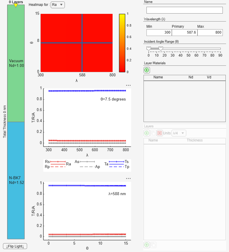
Define Coating Layers
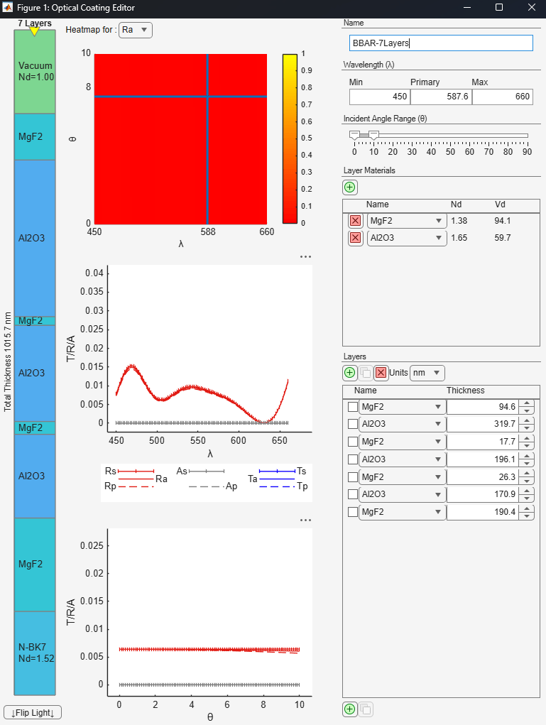
In the optical coating editor, define a seven-layer alternating stack of magnesium fluoride (MgF₂) and aluminum oxide (Al₂O₃) coating materials. The alternating structure of high and low refractive index materials creates destructive interference of reflected light, reducing reflections below the target threshold. The following table lists the layer data in the thin-film coating, from the medium side to the substrate side.
Layer | Material | Thickness (nm) |
|---|---|---|
Medium | Air | — |
1 | MgF₂ | 94.6 |
2 | Al₂O₃ | 319.7 |
3 | MgF₂ | 17.7 |
4 | Al₂O₃ | 196.1 |
5 | MgF₂ | 26.3 |
6 | Al₂O₃ | 170.9 |
7 | MgF₂ | 190.4 |
Substrate | N-BK7 | — |
Configure and Visualize Coating
Specify the wavelength range, incident angle range, and set the name of the coating, Name, to BBAR-7Layers. The transmission plot in the optical coating editor confirms that the reflection across the specified wavelength range is less than 1%, meeting the design target for broadband anti-reflection.
Add Coating to Coating Library
To use the designed coating in the Optical System Designer app, extract the coating from the optical coating editor and add it to the coatingLibrary by using the addCoating function.
bcoat = h.Coating;
cl = coatingLibrary;
addCoating(cl,bcoat);
The BBAR-7Layers coating is now available for selection in the Optical System Designer app.
Import Optical System
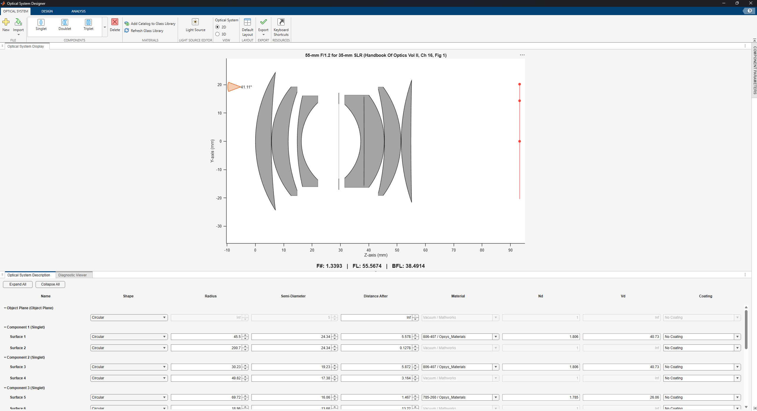
Import a double Gauss optical system by using the zmximport function. The Zemax file is attached to this example as a supporting file.
opsys = zmximport("DoubleGaussLens.zmx");To import the optical system into the Optical System Designer app, specify the opticalSystem object as input to the opticalSystemDesigner function. Alternatively, you can import a ZMX file directly by specifying the file path.
opticalSystemDesigner(opsys)
Analyze Transmission of Uncoated System
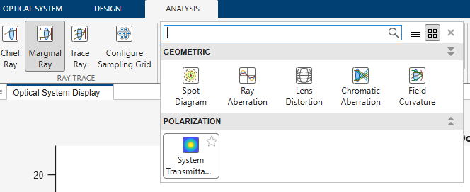
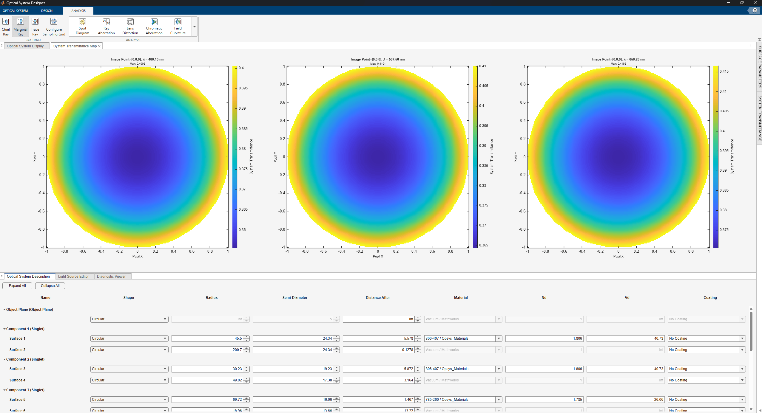
Return to the Optical System Designer app to evaluate the transmission of the uncoated optical system. To generate the system transmission map, select System Transmittance Map in the Analysis section of the Analysis tab.
The app opens the System Transmittance Map chart, which displays the transmission across the entrance pupil of the optical system. The uncoated system has a maximum transmission of approximately 42%, with the remaining light lost to surface reflections at each air-glass interface.
Apply Coatings to Optical System Surfaces
To improve system transmission, apply the BBAR coating to each air-glass interface in the optical system. You can use the optical coating picker or the coating dropdown to apply coatings to individual surfaces.
Apply Coating Using Optical Coating Picker
To apply the BBAR coating to a surface, select the first surface in the Optical System Description panel and locate the Coating dropdown menu.
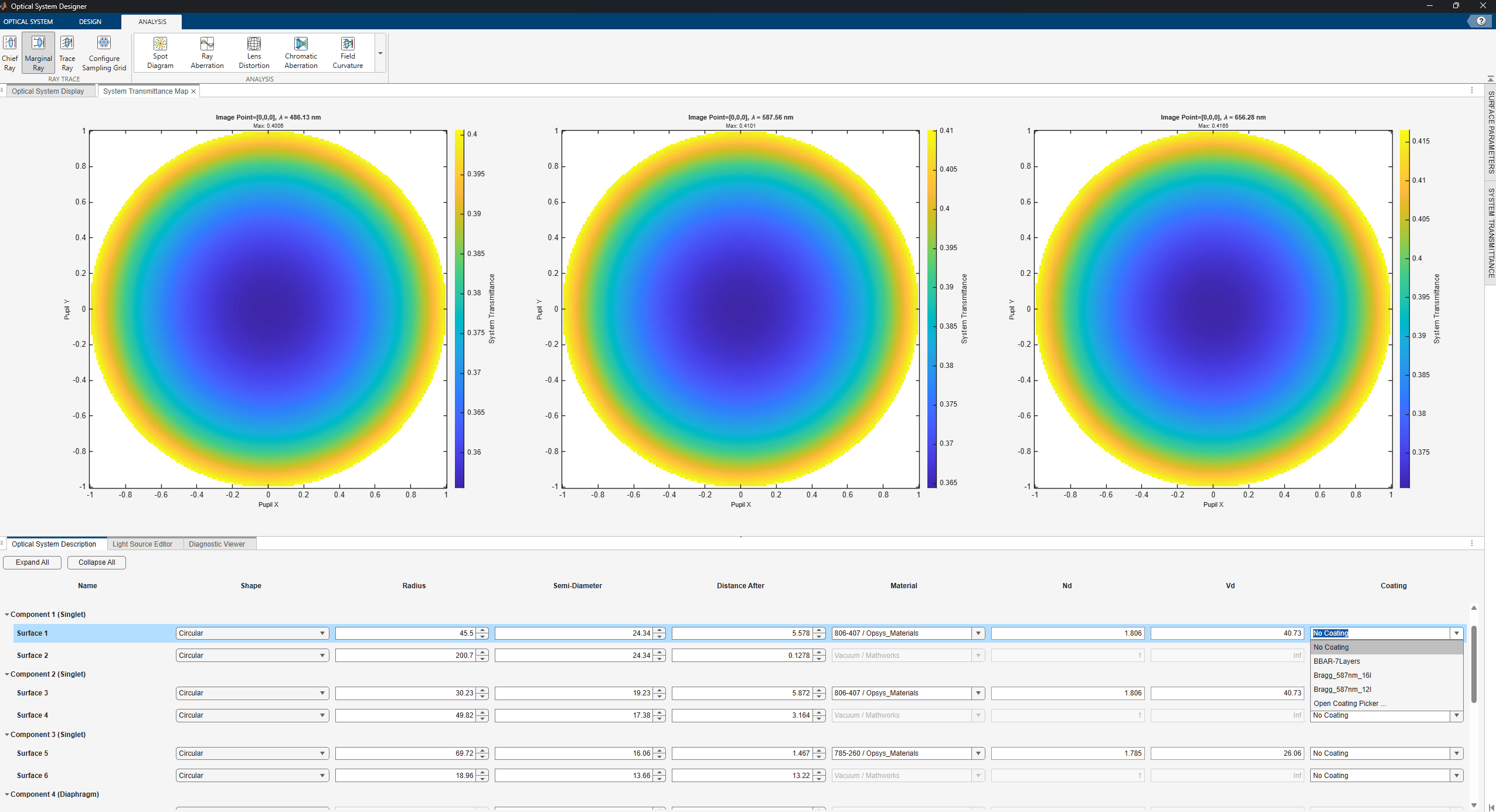
You can either select a coating directly from the dropdown menu or select Open Coating Picker from the dropdown to browse the full coating library.
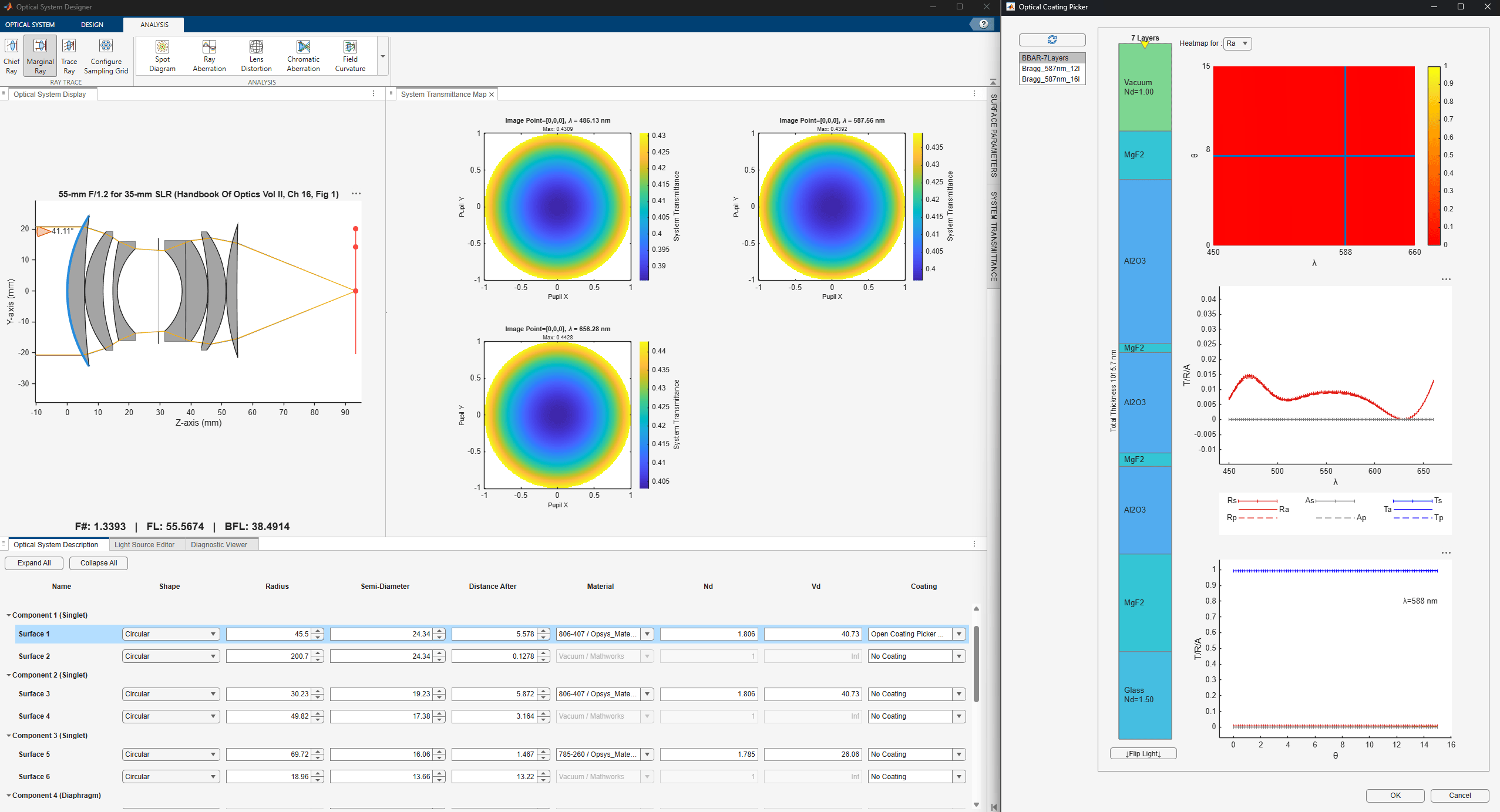
As you hover over different coatings in the coating picker, the displayed system transmission map automatically updates, showing how each coating affects the overall transmission throughput. You can also view the coating layer stack and reflectance plots to evaluate each coating design. This interactive preview helps you select the most effective coating for your design requirements.
Select the BBAR-7Layers coating and apply it to the surface. The surface displays a yellow tint in the visualization, indicating that a coating has been applied.
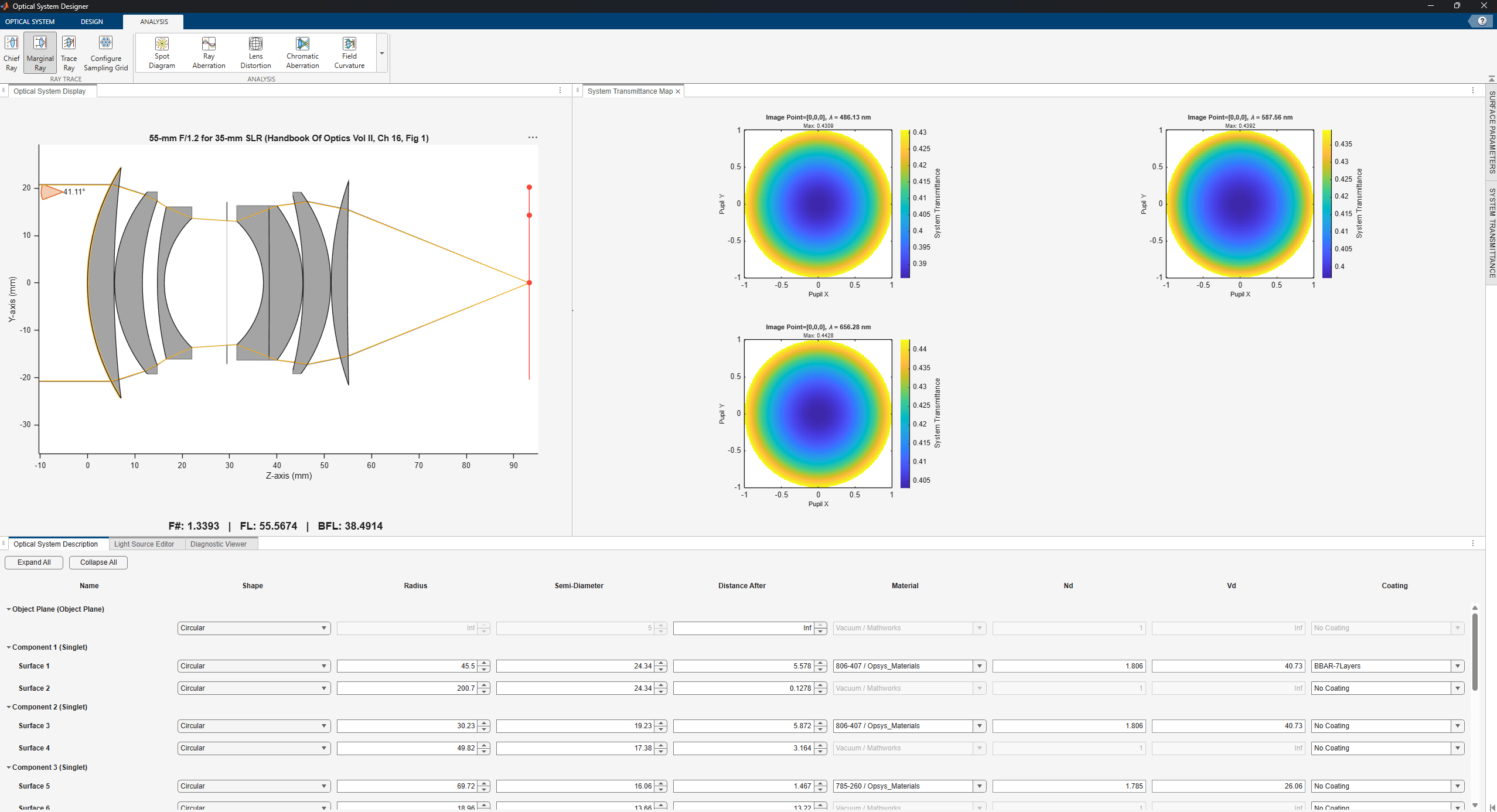
For the remaining lens surfaces in the optical system, apply the BBAR-7Layers coating directly from the Coating dropdown without reopening the picker.
Evaluate Improved System Transmission
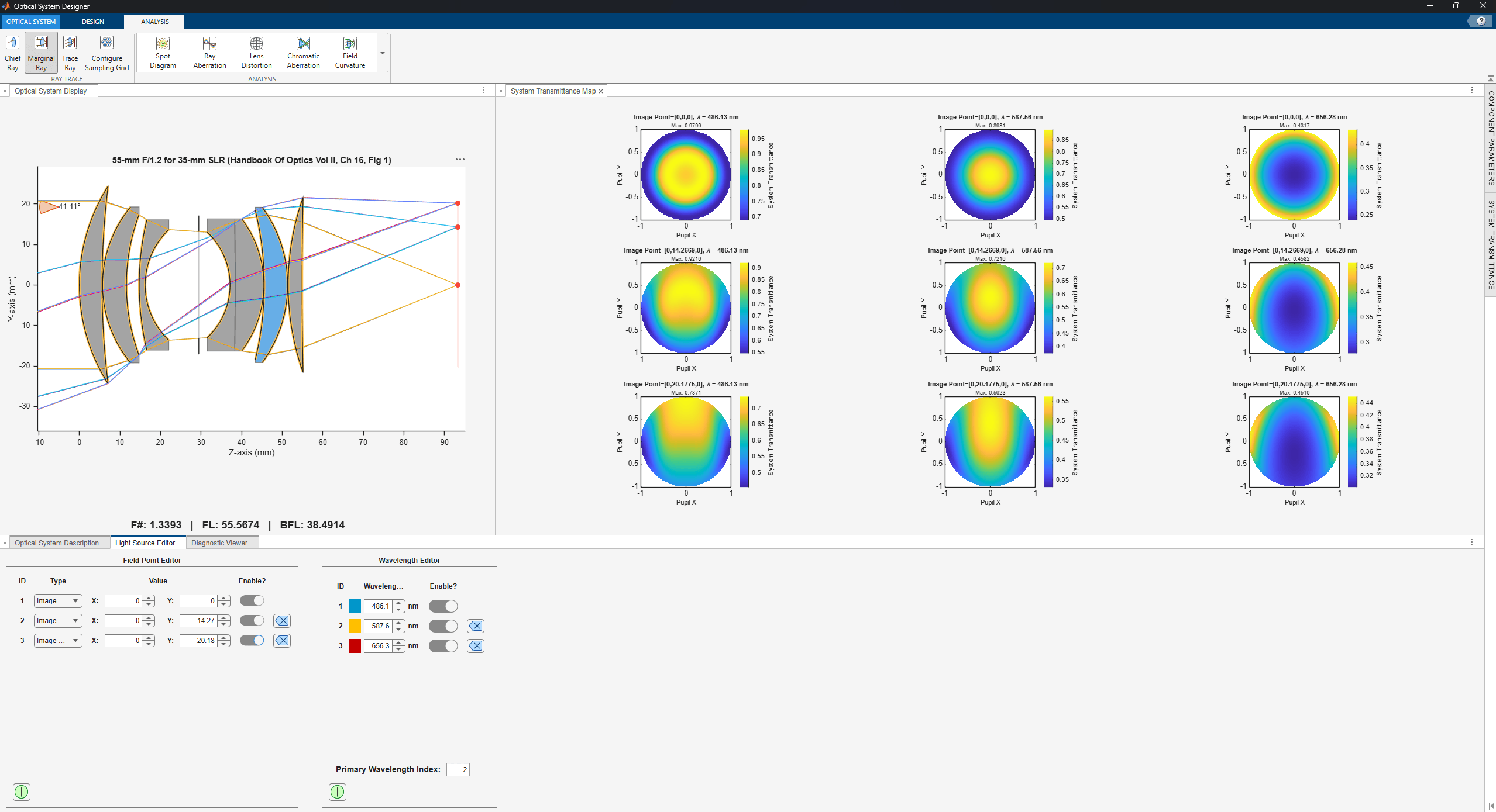
After applying the BBAR coating to all lens surfaces, observe the updated system transmission map. The total transmission improves from approximately 42% to 90%, demonstrating the effectiveness of anti-reflective coatings in minimizing surface reflections and improving the overall transmission throughput of the optical system.
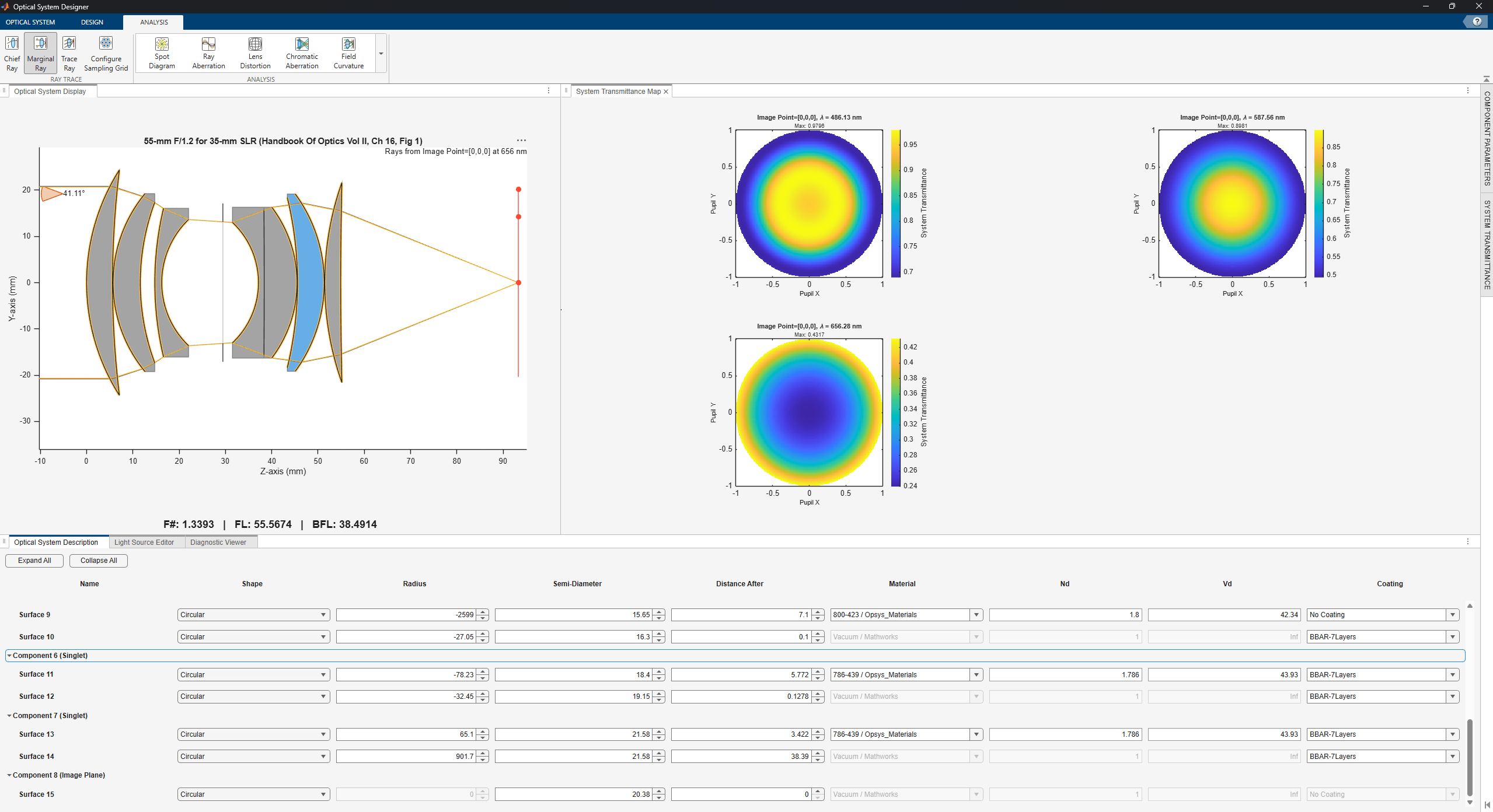
The system transmission map at different field angles and wavelengths confirms consistent improvement across the field of view.
Next Steps
To further optimize your optical system, consider these extensions to the analysis:
Design coatings tailored to specific wavelength bands or angle ranges for narrowband applications.
Experiment with different substrate materials and layer counts to balance manufacturing complexity against reflection performance.
Use the real-time transmission map feedback in the optical coating picker to compare multiple coating designs before committing to a final selection.

