Simulation 3D Agricultural Tractor
R2026bAgricultural tractor with ground following in 3D simulation environment
Since R2026b
Simulation 3D Agricultural Tractor block
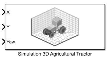
To add a block to a model, double-click the canvas and start typing the block name. Then, select the block from the list.
Libraries:
Offroad Autonomy Library /
Simulation 3D
Description
The Simulation 3D Agricultural Tractor block provides an interface to implement a ground-following agricultural tractor vehicle in the Simulink® 3D world.
Note
Simulating models with the Simulation 3D Agricultural Tractor block requires Simulink 3D Animation™ and the Robotics System Toolbox™ Offroad Autonomy Library support package. For more information about downloading the support package, see Install Robotics System Toolbox Offroad Autonomy Library Support Package.
The agricultural tractor is part of the Offroad Vehicle Library. For more information about the agricultural tractor model, such as its dimensions, see Agricultural Tractor.
Examples
Open the SimulateTractorInRollingVineyardScene Simulink model. The model contains a Simulation 3D Scene Configuration block and a Simulation 3D Agricultural Tractor block. Note that the Rolling Vineyard scene must be installed before you can set it in the Simulation 3D Scene Configuration block. See Rolling Vineyard for instructions on installing the scene.
open_system("SimulateTractorInRollingVineyard");
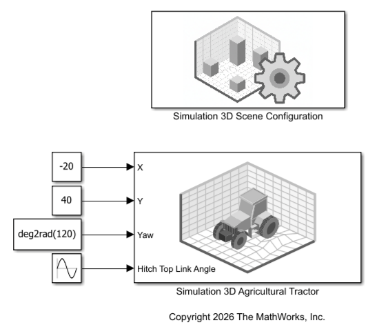
This model places the agricultural tractor at a recommended starting location and oscillates the hitch between its lowest and highest configurations. For more starting locations, see the Recommended Starting Locations section of Rolling Vineyard scene.
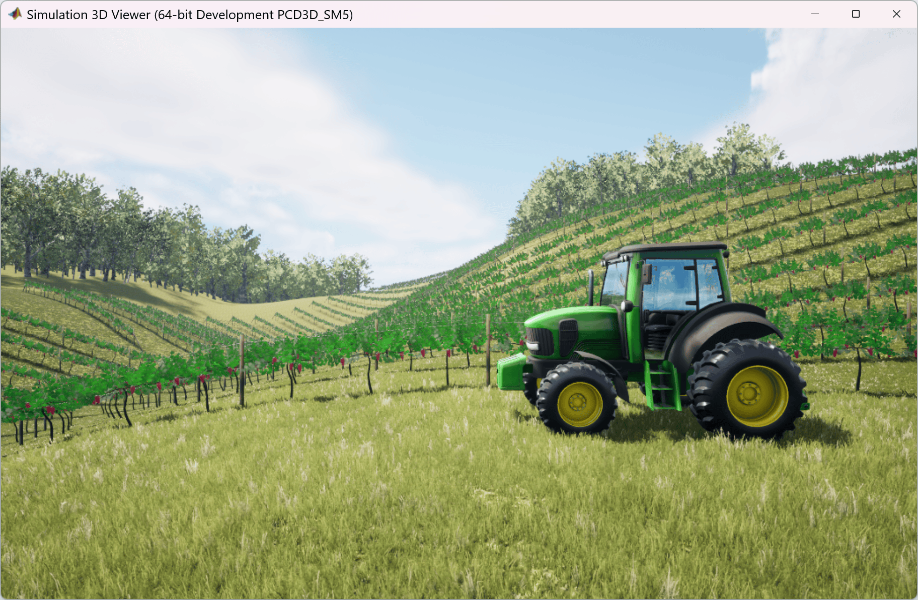
Simulate the model. This figure shows the Simulation 3D Viewer with the view manually set to the left camera view.
sim("SimulateTractorInRollingVineyard.slx");Warning: Support for GPU devices with compute capability 6.1 will be removed in a future MATLAB release. For more information on GPU support, see <a href="matlab:web('http://www.mathworks.com/help/parallel-computing/gpu-computing-requirements.html','-browser')">GPU Computing Requirements</a>.
Ports
Note
Note that this block processes input and output values using the right-hand rule MATLAB® world coordinate system. For more information, see Coordinate Systems for Unreal Engine Simulation in Robotics System Toolbox.
Input
The input ports specify the pose of the rear-axle frame on the agricultural tractor. The x- and y-positions of the origin of the rear-axle frame are centered on the rear-axle, and the z‑position of the frame is aligned with the ground‑contact plane where the rear wheels touch the ground.
x-position of the rear-axle frame of the agricultural tractor in the world coordinate system, specified as a numeric scalar. Units are in meters.
Data Types: double
y-position of the rear-axle frame of the agricultural tractor in the world coordinate system, specified as a numeric scalar. Units are in meters.
Data Types: double
Yaw (z-axis) angle of the rear-axle frame of the agricultural tractor in the world coordinate system, specified as a numeric scalar. Units are in radians.
Data Types: double
Hitch top-link angle, specified as a scalar in the range [0, 1]. A value of
0 sets the top link to the most bottom position. A value of
1 sets the top link to the most vertical position.
Dependencies
To enable this port, select the Enable top link angle input signal parameter.
Output
The Base Translation and Base Rotation output ports return the pose of the origin frame of the agricultural tractor. The x-, y-, and z-position of the origin of the origin frame are centered on the ground‑contact plane where the four wheels touch the ground.
The Hitch Ball Translation and Hitch Ball Rotation output ports return the pose of the agricultural tractor hitch ball frame.
Current ground truth world translation of the origin frame of the agricultural tractor, returned as a three-element row vector of the form [x y z]. The elements of the vector are the translations along the x-, y-, and z-axes, respectively. Units are in meters.
Dependencies
To enable this port, select the Enable ground truth world base translation output signal parameter on the Outputs tab of the block mask.
Data Types: double
Current ground truth world rotation of the origin frame of the agricultural tractor, returned as a 3-by-3 rotation matrix representing the orientation of the origin frame relative to the world frame. The rotation follows the right-hand rule.
Dependencies
To enable this port, select the Enable ground truth world base rotation output signal parameter on the Outputs tab of the block mask.
Data Types: double
Current ground truth world translation of the agricultural tractor hitch ball, returned as a three-element row vector of the form [x y z]. The elements of the vector are the translations along the x-, y-, and z-axes, respectively. Units are in meters.
Dependencies
To enable this port, select the Enable ground truth world hitch ball translation output signal parameter on the Outputs tab of the block mask.
Data Types: double
Current ground truth world rotation of the origin frame of the agricultural tractor hitch ball, returned as a 3-by-3 rotation matrix representing the orientation of the hitch-ball-frame origin relative to the world frame. The rotation follows the right-hand rule.
Dependencies
To enable this port, select the Enable ground truth world hitch ball rotation output signal parameter on the Outputs tab of the block mask
Data Types: double
Parameters
Parameters
Specifies the name of the vehicle as a string scalar. By default, the block sets
the Name parameter to SimulinkVehicle.
The vehicle name appears as an option for the Parent name parameter of any simulation 3D sensor blocks within the same model as the vehicle, enabling you to mount those sensors to the vehicle.
Specifies the color and texture applied to the agricultural tractor as one of these options:
GreenClean— Green tractor with a clean texture.GreenDirty— Green tractor with a dirty texture.BlueClean— Blue tractor with a clean texture.BlueDirty— Blue tractor with a dirty texture.RedClean— Red tractor with a clean texture.RedDirty— Red tractor with a dirty texture.
Clean textures show a model without dirt on the wheels or body and without defects on the hitch or other body parts. Dirty textures show dirt on the wheels and other body parts, and dents and scratches on the hitch and other body parts.
Select this parameter to visualize the ray tracing lines emitted at the tractor wheels. These ray tracers detect the ground under the tractor for ground following.
Specifies the sample time, Ts, as a positive scalar in seconds. The graphics frame rate is the inverse of the sample time.
If you set the sample time to -1, the block uses the sample
time specified in the Simulation 3D
Scene Configuration block.
Initial Values
Specifies the initial translation of the rear-axle frame of the agricultural tractor as a three-element row vector of the form [x, y , z], where x, y , and z are the translations along the x-, y-, and z-axes respectively, using the right-hand rule world coordinate system. Units are in meters.
Specifies the initial rotation of the rear‑axle frame of the agricultural tractor as a 3‑by‑3 rotation matrix. The rotation follows the right‑hand rule in the world coordinate system and represents the orientation of the rear‑axle frame relative to the world frame.
Specifies the initial angle of the agricultural tractor top link as a numeric
scalar in the range [0 1]. A value of 0 sets the top link to the
most bottom position. A value of 1 sets the top link to the most
vertical position.
The default value 3/7 corresponds to a horizontal hitch
configuration, in which the lower hitch crossbar, which has the ball attachment point,
is parallel to the ground. For more details, see Tractor Three-Point Hitch.
Inputs
Select this parameter to enable the Hitch Top Link Angle input port.
Outputs
Select this parameter to output the ground truth world translation of the origin frame of the agricultural tractor at the Base Translation output port.
Select this parameter to output the ground truth world rotation of the origin frame of the agricultural tractor at the Base Rotation output port.
Select this parameter to output the ground truth world translation of agricultural tractor hitch ball at the Hitch Ball Translation output port.
Select this parameter to output the ground truth world rotation of agricultural tractor hitch ball at the Hitch Ball Rotation output port.
More About
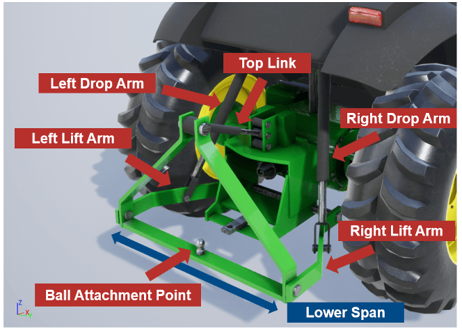
The agricultural tractor hitch is a three‑point linkage used to attach and position implements. These components make up the hitch assembly.
Top Link — Adjustable upper link that connects the tractor to the implement. It controls the implement pitch (fore–aft tilt) and helps stabilize the implement during operation.
Left and Right Lift Arms — Lower arms that raise and lower the implement. Tractor hydraulic system powers these arms and the arms carry most of the implement load.
Left and Right Drop Arms — Vertical linkages that transmit motion from the hydraulic lift mechanism to the lift arms. They convert hydraulic movement into vertical lift of the hitch arms.
Ball Attachment Point — Spherical joints at the ends of the lift arms where the implement pins attach. They allow limited rotation to accommodate terrain and articulation without binding.
Lower Span — The horizontal distance between the left and right lift arms. This span defines implement compatibility and affects hitch stability and load distribution.
"This figure shows the hitch assembly components with the hitch top link at its default position.
Algorithms
The block computes a ground-following pose for the vehicle center by fitting a ground plane to four wheel-contact points and projecting the vehicle frame onto that plane.
The block fits a plane to the four ground-contact points G1, G2, G3, and G4 that the wheel ground-following queries return. The resulting plane satisfies:
where a, b, c, and d are the plane coefficients and (x, y, z) is any point on the plane. The block extracts the unit surface normal:
This normal is perpendicular to the terrain surface and defines the local surface-normal direction.
The goal of this process is to construct a rotation matrix that specifies the orientation of the vehicle in the world frame.
The block projects the vehicle's world-frame heading onto the ground plane to obtain a terrain-aligned forward direction. Starting from the flat-world forward vector based on the rear-axle yaw angle ψ:
The block then finds the unit projection vector f, of fw, parallel to the plane and perpendicular to the plane normal direction:
The block completes the right-handed coordinate frame with a lateral axis and a normal axis u:
The goal of this process is to find the position of the vehicle center projected onto the ground plane.
The block determines the rear-axle elevation by projecting its world-frame coordinates Rx and Ry onto the ground plane:
From the resulting ground-contact point R = [Rx, Ry, z]T, the block offsets to the vehicle origin using Lo (the distance between the rear axle and origin as shown on the vehicle model's dimensions diagram):
The output origin O sits on the ground plane.
The block assembles the orientation and position into a 4-by-4 homogeneous transformation matrix TO:
This transform expresses the vehicle body frame in the world frame, with the vehicle aligned to the local terrain surface.
Version History
Introduced in R2026b
MATLAB Command
You clicked a link that corresponds to this MATLAB command:
Run the command by entering it in the MATLAB Command Window. Web browsers do not support MATLAB commands.
选择网站
选择网站以获取翻译的可用内容,以及查看当地活动和优惠。根据您的位置,我们建议您选择:。
您也可以从以下列表中选择网站:
如何获得最佳网站性能
选择中国网站(中文或英文)以获得最佳网站性能。其他 MathWorks 国家/地区网站并未针对您所在位置的访问进行优化。
美洲
- América Latina (Español)
- Canada (English)
- United States (English)
欧洲
- Belgium (English)
- Denmark (English)
- Deutschland (Deutsch)
- España (Español)
- Finland (English)
- France (Français)
- Ireland (English)
- Italia (Italiano)
- Luxembourg (English)
- Netherlands (English)
- Norway (English)
- Österreich (Deutsch)
- Portugal (English)
- Sweden (English)
- Switzerland
- United Kingdom (English)