主要内容

Simulation 3D Offroad Vehicle

R2026b

Simulate offroad vehicle in 3D simulation environment using rigid body tree model

Since R2026b

  • Simulation 3D Offroad Vehicle Block Icon

Libraries:
Offroad Autonomy Library / Simulation 3D

Description

Add-On Required: This feature requires the Robotics System Toolbox Offroad Autonomy Library add-on.

The Simulation 3D Offroad Vehicle block simulates an offroad vehicle in a 3D simulation environment using a rigid body tree model of the vehicle as input. Use this block to visualize the motion of any custom offroad vehicle, represented as a rigid body tree, in an Unreal Engine® scene.

Specify the vehicle model as a rigidBodyTree object. The rigid body tree defines the bodies of the vehicle, the joints that connect them, and the visual and collision geometries of each body. To drive the motion of the vehicle, supply the base translation, base rotation, and joint configuration as input signals to the block.

Note

Simulating models with the Simulation 3D Offroad Vehicle block requires Simulink® 3D Animation™ and the Robotics System Toolbox™ Offroad Autonomy Library support package. For more information about downloading the support package, see Install Robotics System Toolbox Offroad Autonomy Library Support Package.

To use this block, ensure that the Simulation 3D Scene Configuration block is in your model. The block inherits the sample time specified in the Simulation 3D Scene Configuration block if you set the Sample time parameter of the Simulation 3D Offroad Vehicle block to -1.

Examples

expand all

Use the exampleHelperCreateForklift helper function to create a forklift rigid body tree model. Then load the ground-following parameters, like wheelbase, track width, and wheel radius.

forklift = exampleHelperCreateForklift;
[tw,wb,rad,pose] = exampleHelperForkliftParameters(forklift);
show(forklift,Frames="off")
title("Forklift")
axis auto
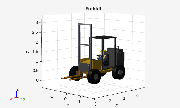
Figure contains an axes object. The axes object with title Forklift, xlabel X, ylabel Y contains 63 objects of type patch.

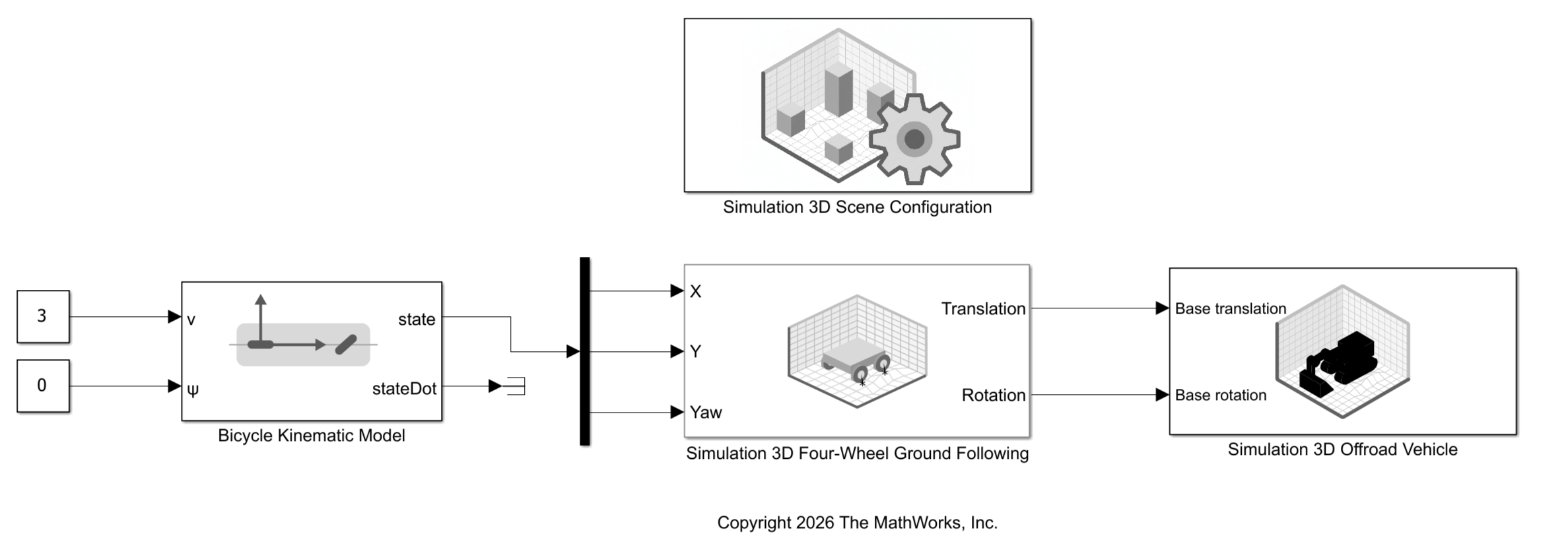
Open the model. In the Simulation 3D Four-Wheel Ground Following block mask, specify all of ground-following parameters for the forklift.

open_system("Sim3DForkliftGroundFollowing.slx")
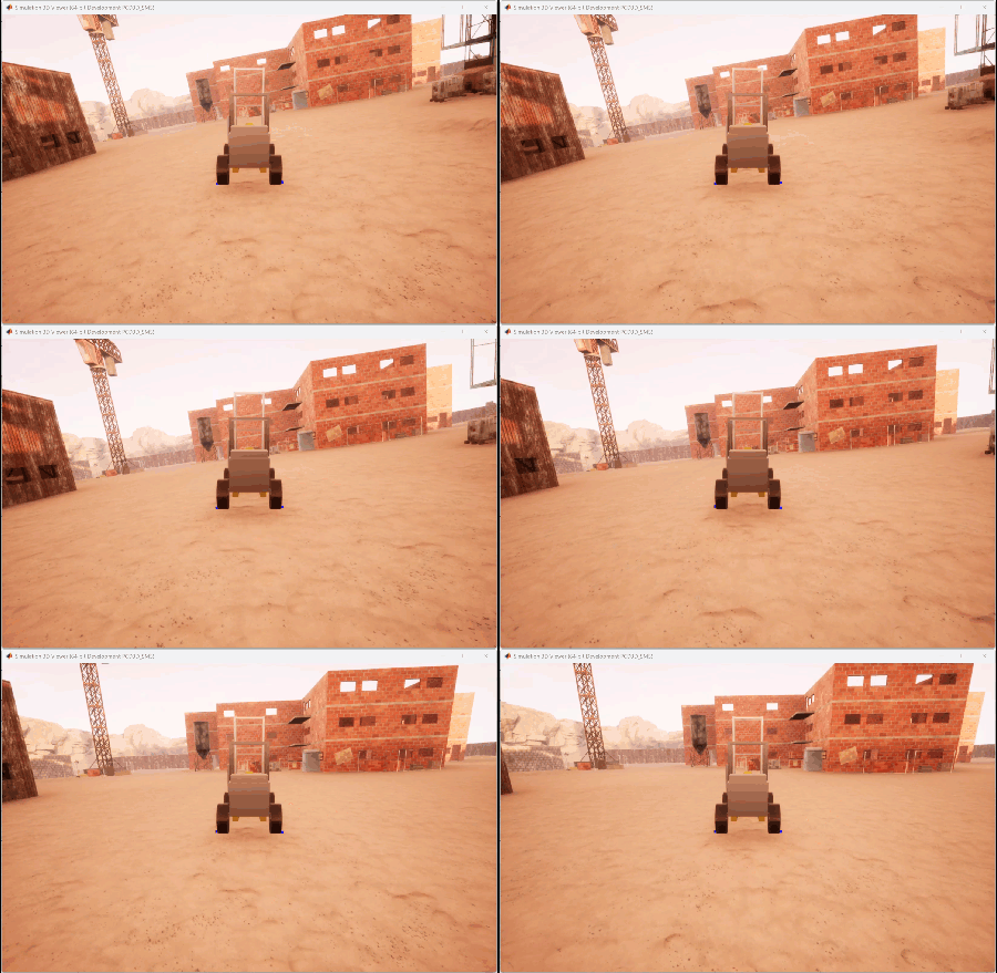
Run the model.

sim("Sim3DForkliftGroundFollowing.slx");
function [tw,wb,rad,pose] = exampleHelperForkliftParameters(forklift) 

homeConfig = homeConfiguration(forklift);

tformRL_RR = getTransform(forklift,homeConfig,"wheel_rr","wheel_rl");
tw = norm(tform2trvec(tformRL_RR));

tformRL_FL = getTransform(forklift,homeConfig,"wheel_fl","wheel_rl");
wb = norm(tform2trvec(tformRL_FL));

tformOrigin_RL = getTransform(forklift,homeConfig,"wheel_rl","origin");
posOrigin_RL = tform2trvec(tformOrigin_RL);
rad = posOrigin_RL(3);

pose = getTransform(forklift,homeConfig,"rear_axle","origin"); 

end

Ports

Note

This block processes all the input values using the right-hand rule world coordinate system. For more information, see Coordinate Systems for Unreal Engine Simulation in Robotics System Toolbox.

Input

expand all

Translation of the vehicle base along the x-, y-, and z-axes, specified as a three-element row vector of the form [x, y, z] in the world coordinate system. Units are in meters.

Dependencies

To enable this port, select the Enable translation and rotation input signals parameter on the Inputs tab of the block mask.

Data Types: single | double

Rotation of the vehicle base, specified as a 3-by-3 rotation matrix representing the orientation of the base relative to the world frame. The rotation follows the right-hand rule.

Dependencies

To enable this port, select the Enable translation and rotation input signals parameter on the Inputs tab of the block mask.

Data Types: single | double

Joint configuration of the vehicle, specified as an N-element vector of joint positions, where N is the number of nonfixed joints in the rigid body tree specified by the Rigid body tree parameter. Each element sets the position of a nonfixed joint, in the joint order defined by the rigid body tree. Units are in radians for revolute joints and meters for prismatic joints.

To view the nonfixed joints and their order, use the homeConfiguration function on the rigid body tree specified by the Rigid body tree parameter. To find which bodies contribute to the nonfixed joints, use the showdetails function on the same rigid body tree.

Dependencies

To enable this port, select the Enable joint configuration input signal parameter on the Inputs tab of the block mask.

Data Types: single | double

Parameters

expand all

To edit block parameters interactively, use the Property Inspector. From the Simulink Toolstrip, on the Simulation tab, in the Prepare gallery, select Property Inspector.

Parameters

Rigid body tree model of the vehicle, specified as a rigidBodyTree object. The rigid body tree defines the bodies of the vehicle, the joints that connect them, and the visual and collision geometries used for visualization. Specify the rigidBodyTree object from the MATLAB workspace.

Name of the vehicle actor in the Unreal Engine scene, specified as a string scalar. The vehicle name appears as an option for the Parent name parameter of any Simulation 3D sensor blocks within the same model as the vehicle. This option enables you to mount those sensors to the vehicle base.

Each Simulation 3D Offroad Vehicle block in a model must have a unique actor name. By default, the block assigns a unique actor name when you add or copy the block. If you specify an actor name that is already in use in the model, the block returns an error.

Select this parameter to use an existing actor in the Unreal Engine scene to represent the vehicle. When you select this parameter, the Simulation 3D Offroad Vehicle block uses the actor in the scene with the name specified by the Actor name parameter. If you clear this parameter, the block creates a new actor with the specified actor name in the scene to represent the vehicle.

Sample time of the block, in seconds, specified as a positive scalar. The 3D simulation environment frame rate is the inverse of the sample time.

If you set the sample time to -1, the block inherits its sample time from the Simulation 3D Scene Configuration block.

Initial Values

Initial translation of the vehicle base, specified as a three-element row vector, in the form [x, y, z]. x, y, and z are the translations along the x, y, and z axes, respectively. Units are in meters.

When the Base translation input port is enabled, the input signal specifies the translation of the base during simulation.

Initial rotation of the vehicle base, specified as a 3-by-3 rotation matrix representing the orientation of the base relative to the world frame. The rotation follows the right-hand rule.

When the Base rotation input port is enabled, the input signal specifies the rotation of the base during simulation.

Initial joint configuration of the vehicle, specified as an N-element vector, where N is the number of nonfixed joints in the rigid body tree specified by the Rigid body tree parameter. Units are in radians for revolute joints and meters for prismatic joints.

When the Joint configuration input port is enabled, the input signal specifies the joint configuration during simulation.

Vehicle Visualization

Set the parameters on this tab to configure the visualization of the rigid body tree visual and collision geometries in the 3D visualization environment.

Visual Geometry Visualization

Select this parameter to add rigid body tree visual geometry in the 3D visualization environment.

Collision Geometry Visualization

Select this parameter to visualize rigid body tree collision geometry in the 3D visualization environment.

Enabling rigid body tree collision visualization from the block overlays Robotics System Toolbox collision geometry in the Unreal Engine scene for visualization only. This visualization does not modify or replace the Unreal Engine collision used for physics simulation.

Color of the rigid body tree collision geometry being visualized in the 3D visualization environment, specified as a three-element row vector of the form [R G B], where each element is in the range [0, 1].

Dependencies

To enable this parameter, select the Enable collision geometry visualization in 3D scene parameter.

Transparency of the rigid body tree collision geometry being visualized in the 3D visualization environment, specified as a scalar in the range [0, 1]. A value of 0 is fully opaque and a value of 1 is fully transparent.

Dependencies

To enable this parameter, select the Enable collision geometry visualization in 3D scene parameter.

Inputs

Select this parameter to specify the translation and rotation of the vehicle base at the Base translation and Base rotation input ports, respectively.

Select this parameter to specify the joint configuration of the vehicle at the Joint configuration input port.

Version History

Introduced in R2026b