Design Camera Perception Component to Detect Bin Items
This example describes one approach to design a perception component for use with a bin picking system.
Bin picking involves using a manipulator to retrieve items from a bin. Intelligent bin picking adds autonomy: Parts are perceived using a camera system, and a planner generates collision-free trajectories that adapt to the scene.
This example shows how to create a perception component that will work with the bin-picking system. The component is stored as a standalone model that can be called as a referenced model in a harness. The example further uses a test harness to validate system behavior.
Review the model
Open the test harness containing the detection model and navigate to the detection subsystem to inspect its contents
open_system('Perception_Harness')
open(Simulink.BlockPath('Perception_Harness/Object Detector'));

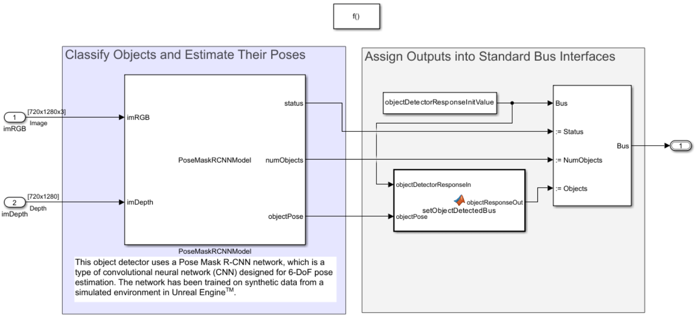
There are two sections, designated in the model by the two areas:
The bulk of the processing happens in the first section, in which the Pose Mask R-CNN feature is used to detect object pose. The second section simply packages the outputs into a defined bus interface so that the module can be easily exchanged with other similar modules. This bus interface is detailed in the Inputs/Outputs section below.
Classify Objects and Estimate their Poses using Pose Mask R-CNN
The main task in this model is to take an image containing all the objects in the bin and return semantic information: bounding boxes of the objects, their classifications, and their poses. While these tasks can be accomplished using a number of trained networks, the Pose Mask R-CNN specifically helps to detect poses of objects. In this case, the network was trained using labeled image from Unreal via the Simulink 3D Animation interface. For more details, see the Perform 6-DoF Pose Estimation for Bin Picking Using Deep Learning (Computer Vision Toolbox) example.
It is important to note that the network here was trained on Unreal Engine® data and therefore works well with an Unreal simulation environment. To scale this network to real hardware, you may need to inject additional labeled images from the actual camera image into the dataset.
Assign Outputs into Standard Bus Interfaces
The model accepts RGB and depth matrices from a depth camera, and returns an object detections bus, which contains information on the status and detected objects. The bus has the structure described below.
While you could replace this module with a completely different one, it would be necessary to use the same buses to communicate when used in the larger module or to update the buses there. Note that the buses have many fields, but only a few are necessary. For example, often bin-picking systems will use an off-the-shelf camera that computes detections using proprietary software. To replace this perception module using such a system, it would be necessary to ensure that the outputs from the system are translated into the object detections bus, so that it could be subsequently replaced in the overall system.
Camera RGB Image and Depth Data
This module accepts inputs from a depth Camera, like the Intel® RealSense™. These are assumed to be a 720-by-1280-by-3 array of RGB values (for a 720-by-1280 pixel camera) and a 720-by-1280 matrix of depth data. If a camera with a different resolution is used, you must update the inports because the size is hard-coded in the parameters to assist with model compilation.
Object Detections Bus
The structure of the bus can be seen from the initialization struct:
busCmdToTest = objectDetectorResponseInitValue;
The bus has three key fields:
The
Statusfield indicates 1 when the perception module completed successfully, and 0 otherwise.The
ObjectDetectionsandNumObjectsfields instruct the reader what the detections are. TheObjectDetectionsoutput is a P-element struct, where P is a fixed value corresponding to the expected maximum number of objects, which should correspond to the fourth bus property,MaxNumObjects. Here, P has a value of 8. At each detection, only a subset of the original maximum may be found, but the dimension of this struct remains the same. Therefore the additional parameter,NumDetections, is used to indicate how many detections to look at.
The ObjectDetections field is itself a bus, and its parameters can be seen from a detailed look at the initial value:
busCmdToTest.Objects
ans=8×1 struct array with fields:
    Name
    Type
    AttachBody
    Radius
    Length
    Color
    Opacity
    Displacement
    EulAnglesZYX
    ObjectPos
    ObjectEulZYX
    PickPos
    PickEulZYX
    ID
While there are a number of possible properties to populate, the following are the most important ones used here:
The
Name,Type, andAttachBodyproperties are used to track the task details. They are stored as fixed-lengthuint8but can be converted to character by using thecharfunction. For example, you can see that the first object name is initialized to empty values by calling the following code snippet:
char(busCmdToTest.Objects(1).Name)
ans =
'                                                                                                                                                                                                                                                                '
The
ObjectPosandEulAnglesZYXproperties specify the object position and orientation (in Euler xyz-sequence), respectively. These two together define the object pose.
There are several optional fields that can be used to pass additional grasping pose information, but those are unused in this module. Additionally, the bus is able to provide information about object color, opacity, etc.
Validate Perception System with Sample Scene
We can validate the detections module using a test harness.
Open and Run the Harness
Start by opening the harness.
open_system("Perception_Harness.slx")
The harness is designed to test the main functionalities that this block must achieve using the known ground truth:
Classify X, L, I, and T PVC parts
Return the poses of those parts
The provided harness does this by first building a bin picking environment and populating it with parts. This environment is a subset of the complete bin picking environment, which also models and controls the robot. However, as the robot is not needed to validate perception, it is not included here. You can learn more about the complete scene creation in the Design Bin Picking Scene and Sensors in Unreal Engine example.
The parts are placed in the initialization script, initRobotModelParams_BinPickingScene.m. The script saves the poses to the variable pose_list. For example, the first initialized object is an I-shape PVC part placed at the xyz-coordinates specified by loc and with orientation (in Euler xyz-coordinates) given by rot.
pose_list(1)
ans = struct with fields:
               loc: [0.4700 -0.1500 0.5700]
               rot: [0 0 0.5236]
        model_path: "Ishape.stl"
        model_name: "Ishape"
    instance_label: 101
In the harness, the object detector system is triggered by a MATLAB Function block that simply does this once. At this instant, object detections are stored to the outport. These can then be compared to the ground truths in the pose_list.
Run the model by clicking play or calling the sim command:
out = sim("Perception_Harness.slx");
Note that this requires the Computer Vision Toolbox Model for Pose Mask R-CNN 6-DoF Object Pose Estimation support package. To install this support package, use the Add-On Explorer. See Get and Manage Add-Ons for more information. If you are unable to install, you can also load an example execution with this code.
if ~exist("out","var")
    load("sampleHarnessOutputData");
end
Validate Model Output
Read the output data, which will be stored as a time series. Choose the final index as the timestamp for comparison.
endSimIdx = length(out.tout);
perceivedObjects = out.yout{1}.Values.Objects;
Iterate over the perceived objects to gather comparison data:
numObj = length(perceivedObjects);
perceivedIDs = strings(1,numObj);
perceivedTrans = zeros(3,numObj);
perceivedRot = zeros(3,numObj);
for i = 1:numObj
    perceivedIDs(i) = perceivedObjects(i).ID.Data(endSimIdx);
    perceivedTrans(:,i) = perceivedObjects(i).PickPos.Data(:,:,endSimIdx);
    perceivedRot(:,i) = perceivedObjects(i).PickEulZYX.Data(:,:,endSimIdx);
end
Next, verify that the types of objects are correctly perceived:
spawnedShapes = [pose_list.model_name]
spawnedShapes = 1×8 string
    "Ishape"    "Ishape"    "Xshape"    "Xshape"    "Lshape"    "Lshape"    "Tshape"    "Tshape"
perceivedShapes = perceivedIDs+"shape"perceivedShapes = 1×8 string
"Lshape" "Ishape" "Ishape" "Tshape" "Xshape" "Xshape" "Lshape" "Tshape"
assert(all(sort(spawnedShapes)==sort(perceivedShapes)))
The next aim is to verify that the object positions are correctly identified. To do this, use the ground truth that was set in the initialization script. This can be read from the pose list. Note that this was place in Simulink 3D, which mirrors the pose about the xz-plane:
groundTruthPositions = [1 -1 1]'.*reshape([pose_list.loc],3,numObj)
groundTruthPositions = 3×8

    0.4700    0.3400    0.5500    0.5700    0.4800    0.3800    0.3800    0.4700
    0.1500   -0.1400   -0.1000    0.1000         0    0.1900   -0.0600   -0.2000
    0.5700    0.5700    0.5700    0.5700    0.5700    0.5700    0.5700    0.5700
Now for each type of ground truth object, verify that a corresponding perceived object exists at a position within a reasonable tolerance of what was expected. You could use a similar approach to verify orientation, but for the current approach of suction-based gripping for objects that are flat along the bin's base, only the position is important since the gripper is symmetric about the z-axis and that is the only possible rotation difference.
for objIdx = 1:numel(pose_list)
    perceivedIdx = find(perceivedShapes==pose_list(objIdx).model_name); % Get indices of all matching perceived types
    perceivedPositions = perceivedTrans(:,perceivedIdx);
    groundTruthPosition = groundTruthPositions(:,objIdx);

    % The perceived positions are set relative to the robot base offset, so
    % this must be added back to match the ground truth
    perceivedPositions = perceivedPositions+robotInitialBaseTranslation';

    % Verify that at least one of the matching object poses falls within
    % allowable position tolerances
    allerrdist(objIdx) = min(vecnorm(groundTruthPosition-perceivedPositions,2,1)); %#ok<SAGROW>

    % For picking on a flat bin, the most important criteria is actually
    % the xy-position:
    xyerrdist(objIdx) = min(vecnorm(groundTruthPosition(1:2)-perceivedPositions(1:2,:),2,1)); %#ok<SAGROW>
end
Verify that for each perceived type, the measured part was placed within a reasonable tolerance of the ground truth. The 2-norm between the actual and measured xy-position is given by the variable xyerrdist.
xyerrdist % 2-norm of xy-error, in metersxyerrdist = 1×8
0.0032 0.0027 0.0028 0.0039 0.0061 0.0113 0.0048 0.0102
Verify that this falls within a reasonable tolerance.
postol = 0.015; % Error norm (m)
assert(all(xyerrdist<=postol))
This harness could further be adapted for other verifications. The model it tests is referenced again in the complete example, Intelligent Bin Picking System in Simulink, which shows how to use this perceived output as part of a complete bin picking solution.