Estimate Pose of Fixed Camera Relative to Robot Base
In pick-and-place tasks, such as bin picking, it is common for cameras to be mounted to a fixed position in the environment to enable robot manipulators detect the objects in the workspace. The essential perception pipeline uses this camera to estimate the pose of a target object relative to the camera frame. This pose is then transformed to the base frame of the robot, enabling the robot to successfully pick the object with the end effector. To transform the pose of the object to the robot base frame, you must first determine the pose of the camera with respect to the robot base. This figure shows this kind of pick-and-place configuration and the desired homogeneous transformation matrix, TCameraToBase, which transforms poses in the camera frame to the robot base frame.
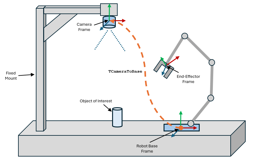
Determining the exact pose of the camera frame presents challenges due to these factors:
Camera manufacturers usually do not mark the camera frame directly on the device, nor do they provide specifications or physical indicators for it. Moreover, the frame relevant for pick-and-place operations is not the camera frame itself but rather a frame situated at the center of the image sensor or plane.
Estimations that assume the camera frame is centered around the lens and rely on manual measurements with a ruler are prone to inaccuracies.
Given these challenges outlined, this example shows the process of determining the transformation matrix, the pose of the camera mounted on a beam relative to the robot's base, by employing the hand-eye calibration workflow.
This example is related to the Estimate Pose of Moving Camera Mounted on a Robot (Computer Vision Toolbox) example, which shows the calibration process for a robot arm with a camera mounted directly on the robot arm, known as Eye-in-Hand or the moving camera configuration. This example shows how to solve for the camera calibration problem for the Eye-to-Hand or the stationary camera configuration. For more information about hand-eye calibration, see What Is Robot Hand-Eye Calibration? (Computer Vision Toolbox).
Estimate Camera Intrinsics
Understanding the intrinsic parameters of the camera, such as its focal length and optical center, is crucial for accurately interpreting images. This example provides the camera intrinsics for this setup in the estimateCameraPoseWrtRobotBase.mat file. However for a different camera and setup, you must determine the camera intrinsics before collecting hand-eye calibration data. You can use the Camera Calibrator (Computer Vision Toolbox) app to estimate these parameters for a fixed camera. For more details about how to use this app, see Using the Single Camera Calibrator App (Computer Vision Toolbox).
Collect Hand-Eye Calibration Data
To collect the calibration data for hand-to-eye configurations, you must follow these steps:
Mount the calibration board on the end effector of the robot.
Move the robot to a configuration in which the calibration board pattern is fully visible to the mounted camera.
Capture the image of the calibration board from the camera and record the corresponding joint configuration of the robot.
Repeat Steps 1-3 to collect at least 15 such images and the corresponding robot joint configurations.
For this example setup, the calibration data has already been collected in the calibrationData.zip file. It contains both the calibration images and the corresponding robot joint configurations.
Unzip the calibration data and display all the calibration images.
unzip("calibrationData.zip")
calibimgds = imageDatastore('calibrationData/*.jpg');
figure(Name="Calibration Images")
montage(calibimgds);
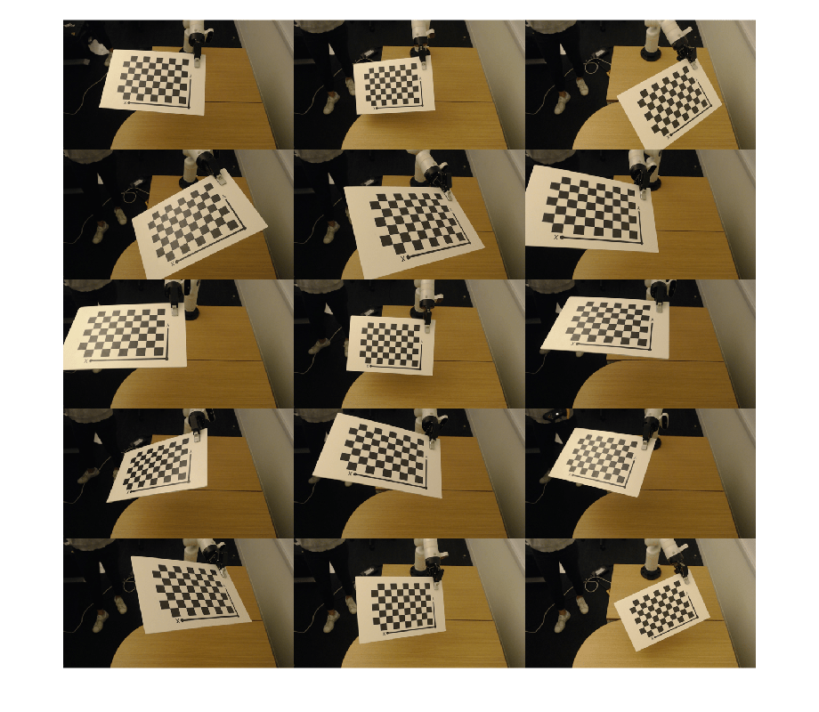
Load and display the corresponding joint configurations from the jointAngles.mat file. The row number of each joint configuration aligns with the name of the corresponding calibration image. For example, the 10th row of jointAngles corresponds to calibration image 10.jpg. The joint angles are measured in degrees.
load("calibrationData/jointAngles")
disp(jointAngles)
346.8241 352.5997 191.5695 212.1722 355.5775 38.5151 184.8700
346.8241 352.5996 191.5695 212.1724 355.5776 20.6987 184.8699
346.8241 352.5996 191.5695 212.1723 355.5775 55.1762 184.8699
346.8241 352.5996 191.5695 212.1723 355.5775 55.1761 159.7137
344.9588 352.5997 191.5695 212.1723 355.5775 47.9125 202.4223
344.9591 350.7478 191.5696 212.1723 334.9004 43.3278 191.6003
344.9592 350.7479 191.5696 212.1722 22.5804 43.3278 191.6003
344.9592 350.7477 191.5696 212.1723 14.6105 17.6080 191.6004
344.9592 350.7478 191.5696 212.1723 65.1178 27.7940 121.8693
9.4972 350.7477 191.5696 212.1723 65.1178 27.7940 121.8693
2.4139 356.8379 179.3088 225.4389 79.5231 35.3008 125.8531
15.2262 356.8380 179.3092 225.4386 48.9265 55.5291 125.8531
15.2261 4.5792 179.3092 225.4386 48.9264 55.5291 175.2737
31.0168 4.5793 179.3092 225.4386 48.9263 55.5291 174.4471
34.9532 358.5155 179.3093 225.4386 48.9264 55.5294 145.9294
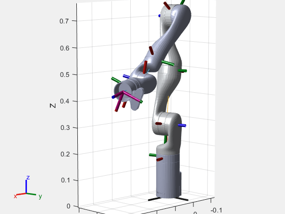
To visualize the robot in a certain joint configuration, load the corresponding robot model and visualize the robot model with the desired joint configuration.
Load the rigid body tree robot model for the KINOVA® Gen3 robot and visualize it in the 7th joint configuration.
figure
kinova = loadrobot('kinovaGen3',DataFormat="row");
show(kinova,deg2rad(jointAngles(7,:)));
title("Joint Angles in 7th Configuration")
axis equal
Compute Camera Extrinsics and End-Effector Poses
The hand-to-eye calibration problem requires several sets of poses. Each set comprises two poses:
1. The camera extrinsics, which is the pose of the checkerboard's origin with respect to the camera.
2. The end-effector pose with respect to the robot base frame.
You can derive both of these poses using the calibration images and the corresponding joint configurations.
Estimate Camera Extrinsics
First calculate the camera extrinsics, the homogeneous transformation matrix, TWorldToCamera.
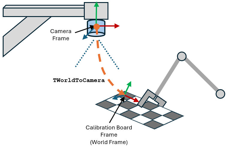
Create the camextrinsics vector for storing the camera extrinsics of each calibration image.
numimgs = length(calibimgds.Files);
camextrinsics = repmat(rigidtform3d,1,numimgs);
Before you can estimate the camera extrinsics, you must determine the intrinsic parameters of the camera and the size of the checkerboard squares in each calibration image. In this example, both the intrinsic parameters and the size of the checkerboard squares have already been computed. For more information about computing the camera intrinsics, see the Single Camera Calibration example on the estimateCameraParameters (Computer Vision Toolbox) function page.
Load the camera intrinsic parameters and the checkerboard square size.
load("estimateCameraPoseWrtRobotBase","intrinsics");
load("estimateCameraPoseWrtRobotBase","checkerboardSquareSizeInMeters");
For each image in your dataset, calculate the camera extrinsics. This estimation requires the calibration image, corrected for any distortion, and the position of the checkerboard points in the world frame. Then use these data to estimate the pose of the camera.
for r = 1:numimgs

    % Load and undistort each calibration image based on precomputed intrinsics.
    fname = fullfile('calibrationData',string(r)+".jpg");
    checkerboardImage = imread(fname);
    checkerboardImageUndistorted = undistortImage(checkerboardImage,intrinsics);

    % Detect the checkerboard corners, discarding partial detections.
    [imgpts,boardsz] = detectCheckerboardPoints(checkerboardImageUndistorted,PartialDetections=false);

    % Generate world coordinates of checkerboard points based on board size and square size.
    worldpts = patternWorldPoints("checkerboard",boardsz,checkerboardSquareSizeInMeters);

    % Estimate the camera extrinsics (pose) from image points and world points.
    camextrinsics(r) = estimateExtrinsics(imgpts,worldpts,intrinsics);
end
Compute End-Effector Poses
Next, use forward kinematics to calculate the pose of the end effector of the robot with respect to the base frame of the robot. The homogeneous transformation matrix representing this pose is TEndEffectorToBase.
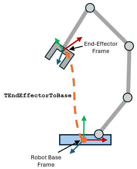
Record the end-effector poses with respect to the robot base frame in TEndEffectorToBase vector.
TEndEffectorToBase = repmat(rigidtform3d,1,numimgs);
For each joint configuration, apply forward kinematics by using the getTransform function. This calculates the pose of the "EndEffector_Link" body of the robot with respect to the base frame of the robot.
for r = 1:numimgs
    jointconfig = deg2rad(jointAngles(r,:));
    TEndEffectorToBase(r) = getTransform(kinova,jointconfig,"EndEffector_Link");
end
Solve Calibration Problem
With the camera extrinsics and end-effector poses from the calibration data, estimate the pose of the camera with respect to the base of the robot.
TCameraToBase = estimateCameraRobotTransform(camextrinsics,TEndEffectorToBase,"stationary-camera");Next, calculate the position of the calibration checkerboard points with respect to the robot base frame.
TWorldToBase = rigidtform3d(TCameraToBase.A*camextrinsics(end).A);
worldpts3d = transformPointsForward(TWorldToBase,[worldpts,zeros(size(worldpts,1),1)]);
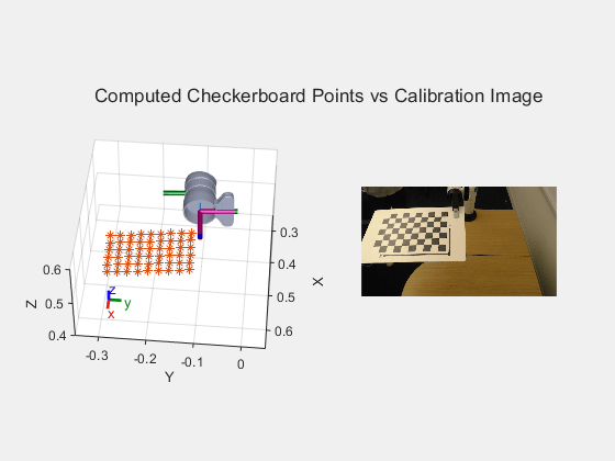
Visualize the robot with the checkerboard points and zoom in to compare it to the calibration image.
tiledlayout(1,2)
nexttile
show(kinova,deg2rad(jointAngles(r,:)));
hold on
scatter3(worldpts3d(:,1),worldpts3d(:,2),worldpts3d(:,3),'*')
view(95,45)
axis([-0.05 0.95 -0.65 0.35 0.25 0.75])
zoom(2.5)
hold off
nexttile
imshow("calibrationData/"+string(r)+".jpg")
sgtitle("Computed Checkerboard Points vs Calibration Image")
Visualize Camera Frame Relative to Robot Base Frame
Plot the camera, robot, and the checkerboard grid points resolved in the robot base frame.
figure
show(kinova,deg2rad(jointAngles(r,:)));
hold on
scatter3(worldpts3d(:,1),worldpts3d(:,2),worldpts3d(:,3),'*')
plotCamera(AbsolutePose=TCameraToBase,Size=0.05,Label="Fixed Camera");
title("Estimated Camera Frame With Respect to Robot Base")
view([-40,10])
zoom(1.5)
axis equal
hold off
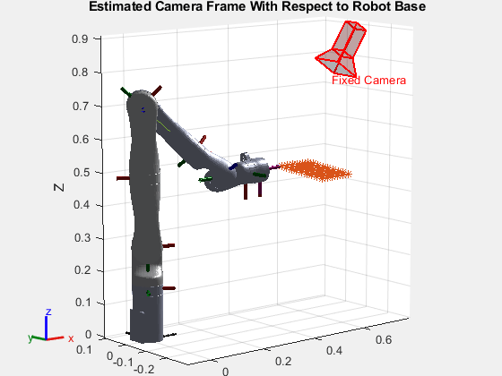
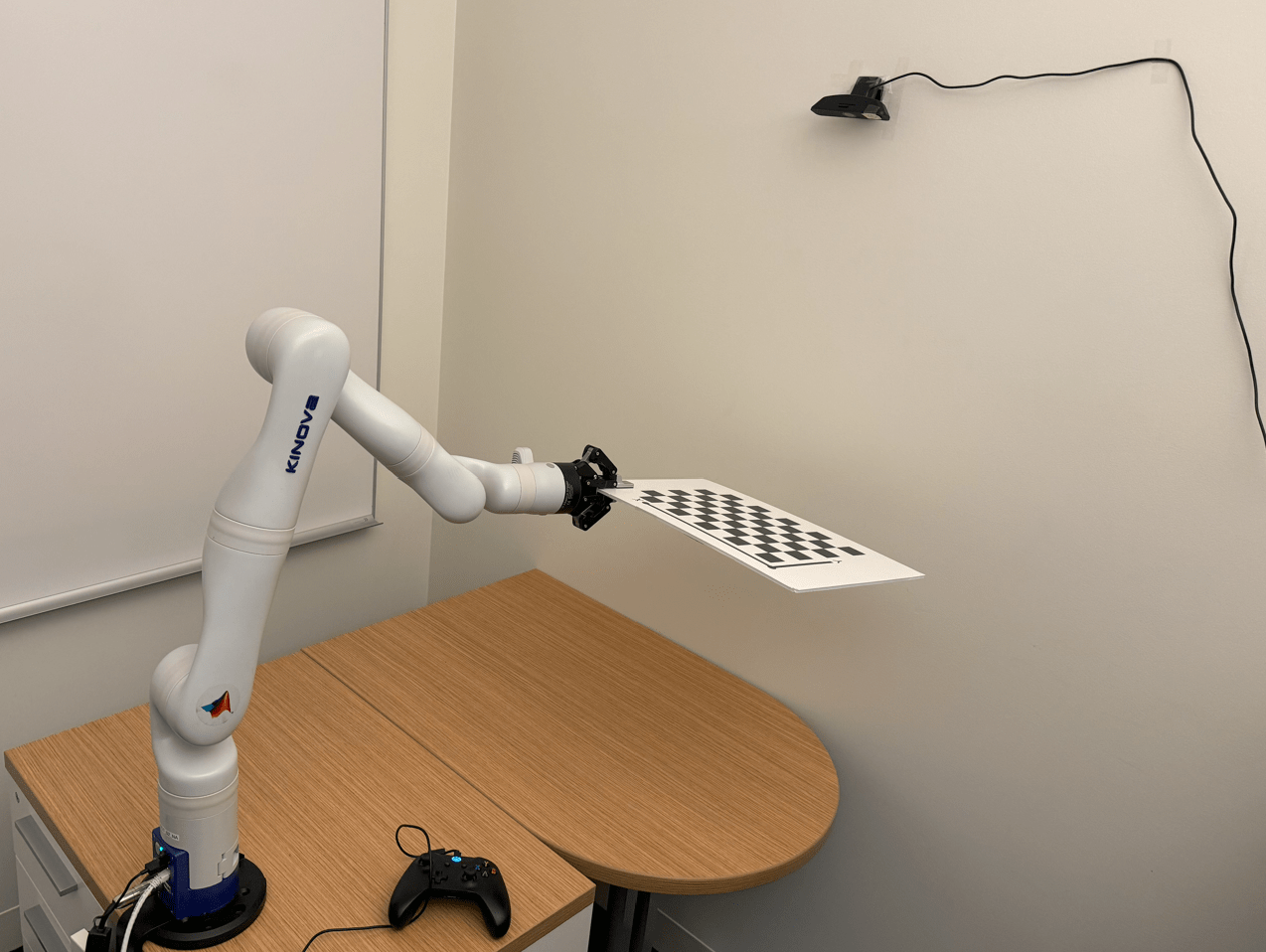
Comparing with the real setup shows that the estimated camera pose, with respect to the robot base, is correct.
Copyrights 2024 The MathWorks, Inc.
See Also
Camera Calibrator (Computer Vision Toolbox) | estimateExtrinsics (Computer Vision Toolbox) | getTransform