电气系统
R2026b浏览关于电气系统建模、控制和仿真的示例。
类别
- Simulink 和 Simscape 中的电路
Simulink® 和 Simscape™ 中的电路示例
- 电池
电池示例
精选示例
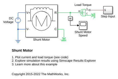
并励电机
此示例展示了一个并励电机的模型。在并励电机中,励磁绕组和电枢绕组是并联连接的。等效电路参数为电枢电阻 Ra = 110 ohm、励磁电阻 Rf = 2.46 KOhm 和反电动势系数 Laf = 5.11。反电动势通过 Laf*If*Ia*w 得出,其中 If 是励磁电流,Ia 是电枢电流,w 是转子转速,单位为 rad/s。转子惯量 J 为 2.2e-4kgm^2,转子阻尼 B 为 2.8e-6Nm/(rad/s)。
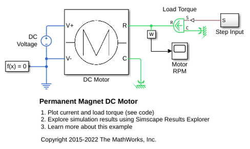
永磁 DC 电机
此示例展示了如何使用测试框架和 Simscape™ 模块来验证 DC 电机的空载转速、空载电流和堵转转矩制造商规格。
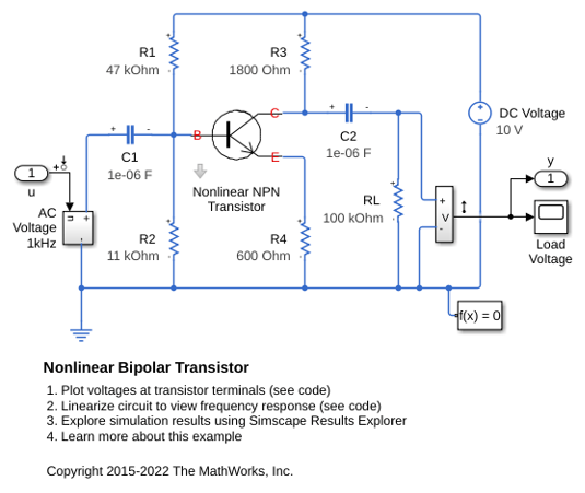
非线性双极晶体管
此模型展示了一个基于 Ebers-Moll 等效电路的非线性双极晶体管的实现。R1 和 R2 设定标称工作点,小信号增益由比值 R3/R4 近似设定。选择了 1uF 去耦电容器,它在 1KHz 时的阻抗可以忽略不计。该模型被配置为线性化,以便产生频率响应。
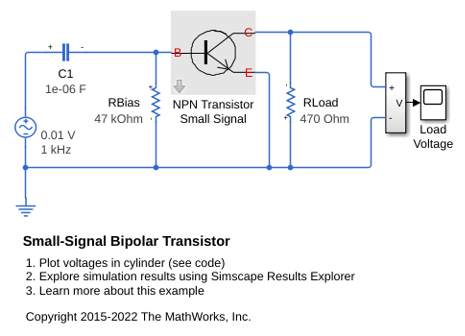
小信号双极晶体管
此模型展示如何使用小信号等效晶体管模型来评估共发射极放大器的性能。47 千欧姆电阻是设置标称工作点所需的偏置电阻,470 欧姆电阻是负载电阻。该晶体管由混合参数等效电路表示,电路参数为 h_ie(基极电路电阻)、h_oe(输出导纳)、h_fe(正向电流增益)和 h_re(反向电压传输比)。所设置的参数是 BC107 B 组晶体管的典型参数。增益约为 -h_fe*470/h_ie =-47。选择了 1 uF 去耦电容器,与输入电阻 h_ie 相比,它在 1 KHz 时的阻抗可以忽略不计,因此输出电压应为 47*10 mV = 0.47 V 峰值。
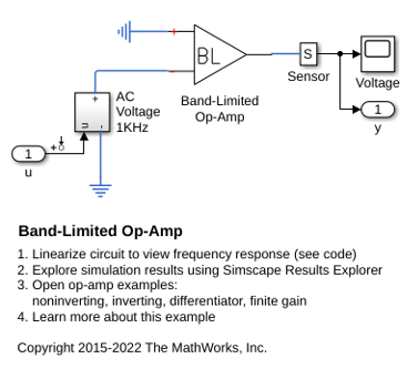
带限运算放大器
此示例展示如何使用 Foundation 库模块构建保真度更高或更详细的组件模型。该模型实现一个带限运算放大器。它包含从输入到输出的一阶动态特性,与使用通常包含多个晶体管的器件级等效电路相比,仿真速度要快得多。该模型还考虑了输入阻抗和输出阻抗(电路中的 Rin 和 Rout)的效应,但并未包含压摆率限制等非线性效应。
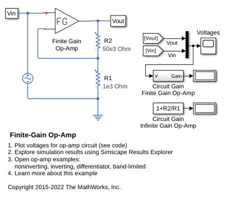
Finite-Gain Op-Amp
How higher fidelity or more detailed component models can be built from the Foundation library blocks. The Op-Amp block in the Foundation library models the ideal case whereby the gain is infinite, input impedance infinite, and output impedance zero. The Finite Gain Op-Amp block in this example has an open-loop gain of 1e5, input resistance of 100K ohms and output resistance of 10 ohms. As a result, the gain for this amplifier circuit is slightly lower than the gain that can be analytically calculated if the op-amp gain is assumed to be infinite.
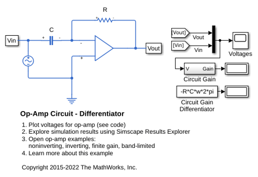
运算放大器电路 - 微分器
该模型展示了一个微分器,这种微分器可以作为 PID 控制器的一部分使用。它还说明了在一些理想化电路中如何会出现数值仿真问题。该模型在电容器串联寄生电阻设为默认值 1e-6 ohm 的情况下运行。将该值设为零会导致出现警告并且仿真速度非常慢。有关详细信息,请参阅用户指南。
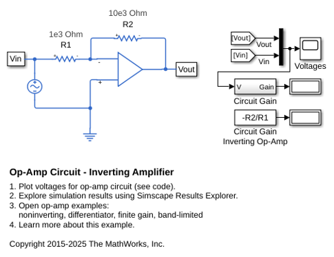
运算放大器电路 - 反相放大器
此示例展示了一个标准反相运算放大器电路的模型。增益由 -R2/R1 给出。当 R1 = 1K Ohm 且 R2 = 10K Ohm 时,0.1 V 的输入电压峰间值被放大到 1 V 峰间值。由于 Op-Amp 模块实现了一个理想的(无限增益)期间,因此无论输出负载如何,都会获得此增益。
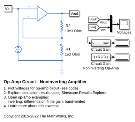
运算放大器电路 - 同相放大器
此模型显示了一个同相运算放大器电路。增益由 1+R2/R1 给出,当值设为 R1=1K Ohm 和 R2=10K Ohm 时,0.1V 的输入电压峰间值被放大到 1.1V 峰间值。由于运算放大器模块实现了一个理想的(即无限增益)设备,因此无论输入负载如何,都会获得此增益。
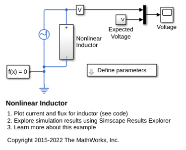
非线性电感器
此示例展示了非线性电感器的实现,其中电感取决于电流。tanh 函数定义非线性磁通-电流关系。磁通会在较大的电流下饱和,例如,在铁芯电感器中会出现这种情况。
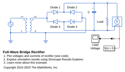
全波桥式整流器
此示例说明如何为将 120 VAC 转换为 12 VDC 的变压器中的特定负载指定电容器大小。系统建模为一个理想的 AC 变压器加全波桥式整流器。
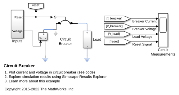
断路器
此示例展示如何对断路器进行建模。机电断路器机构用一个一阶时间常数来近似模拟,并假设机械力和负载电流成正比。这个简单的表示形式适合在一个完整系统的较大模型中使用。在一秒内施加 20V 的电源时,会导致电流超过断路器的额定电流,从而使断路器跳闸。然后,按复位键三秒,电压上升。接着,当电流超过断路器额定电流时,断路器再次跳闸。
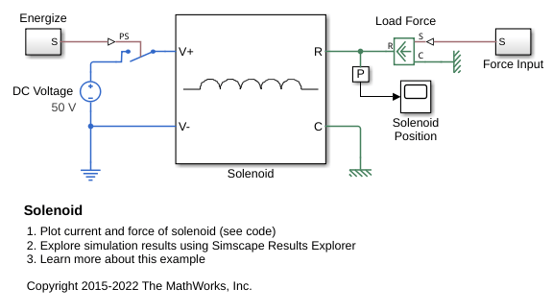
电磁铁
此示例展示了一个带有弹簧复位的电磁铁。该电磁铁被建模为一个电感,其值 L 取决于柱塞位置 x。时变电感的反电动势为:
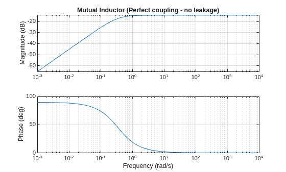
A Comparison of the Mutual Inductor and Ideal Transformer Library Blocks
The differences in behavior between the Mutual Inductor and Ideal Transformer blocks in the Simscape™ Foundation Library. These two blocks both represent the same system of electromagnetically-coupled windings but make different simplifying assumptions. It is important to understand the assumptions and how they impact model fidelity as a function of frequency. With this, you can make an informed decision about which block to use in a model of your circuit.
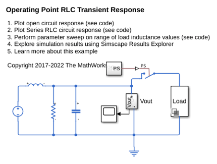
Operating Point RLC Transient Response
The response of a DC power supply connected to a series RLC load. The goal is to plot the output voltage response when a load is suddenly attached to the fully powered-up supply. This is done using a Simscape operating point.

