转换器(高功率)
利用这些示例了解如何对用于高功率应用(高于 48 V)的转换器进行建模。
精选示例
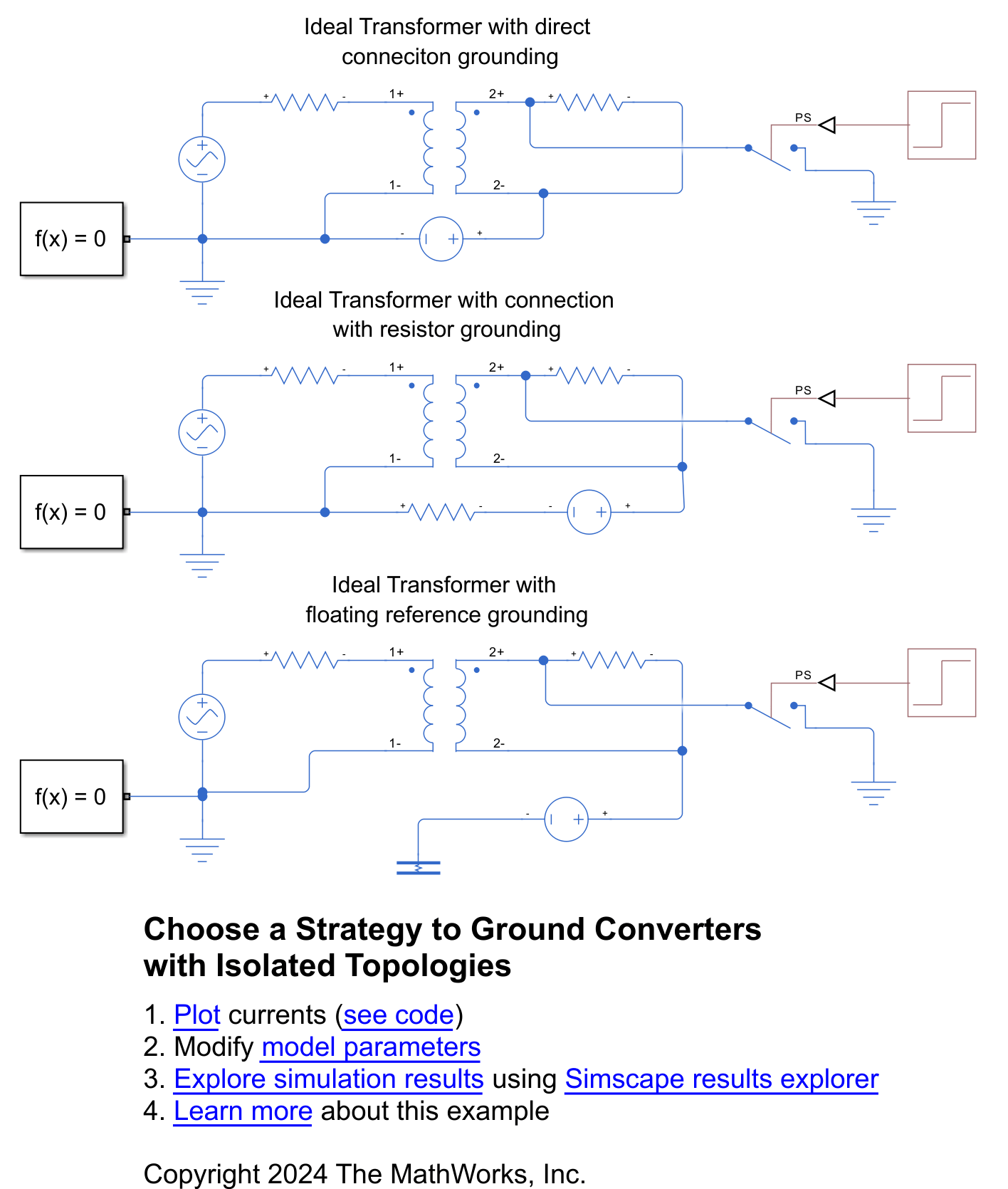
Choose Strategy to Ground Converters with Isolated Topologies
Correctly ground isolated topologies, such as electrical power converters with galvanic isolation. You compare three methods of grounding an ideal transformer and choose the best option depending on your application.

Model High-Voltage Direct-Current Transmission Using Modular Multilevel Converters
Models a high-voltage, direct-current (HVDC) transmission system using modular multilevel converters (MMC).
18 脉冲二极管整流器建模
此示例展示了如何对 18 脉冲二极管整流器建模以减少线电流谐波。
24 脉冲二极管整流器建模
此示例展示了如何对 24 脉冲二极管整流器建模以减少线电流谐波。
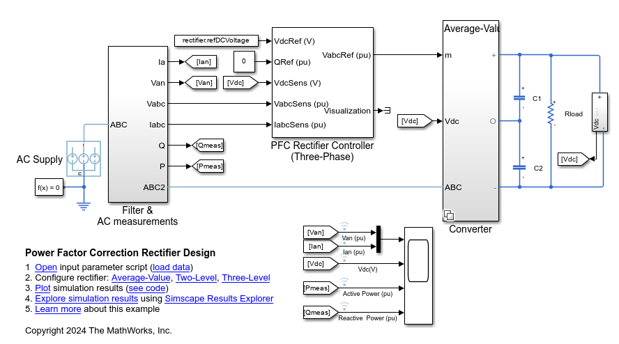
功率因子校正整流器设计
此示例展示了如何将三相 AC 电源电压转换为稳定的 DC 母线电压,并控制从电网汲取的无功功率。为了减少系统中的谐波,请使用 PFC Rectifier Controller (Three-Phase) 模块来生成正弦电流。
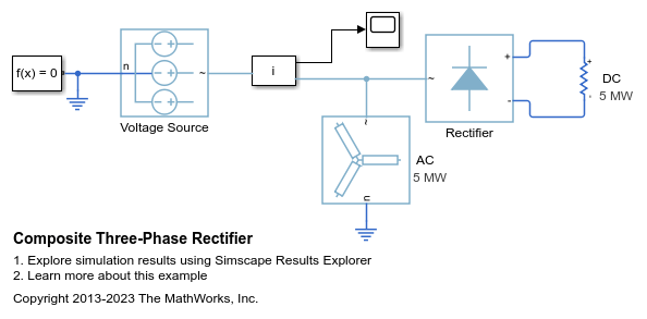
复合三相整流器
这是分析工作流示例的基础模型。

负载侧转换器控制
此示例展示了如何控制负载侧转换器中的 RMS 电压。负载由三相串联 RL 元件提供。Control 子系统采用基于 PI 的级联控制结构,包含两个控制环:一个外层电压控制环和一个内层电流控制环。仿真使用阶跃参考信号。Scopes 子系统包含示波器,可用于查看仿真结果。
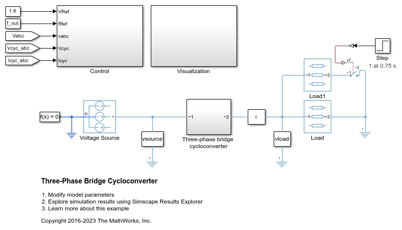
三相桥式循环转换器
此示例展示了一个三相桥式循环转换器。该循环转换器由 36 个晶闸管组成,能够降低输入电压的频率。Control 子系统实现循环转换器 RMS 控制。该子系统还为晶闸管的触发提供脉冲生成。Visualization 子系统包含示波器,可用于查看仿真结果。仿真时间 t 为 1 秒。在 t = 0.75 秒时,Load1 导通,负载增加。
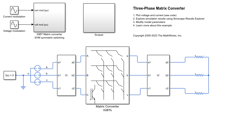
三相矩阵转换器
此示例展示了一个三相矩阵转换器,该转换器驱动静力荷载并在源端实现单位功率因子。Scopes 子系统包含示波器,可用于查看仿真结果。

三相模块化多电平转换器
此示例展示了如何对三相模块化多电平转换器 (MMC) 进行开环控制。每个 MMC 臂由四个半桥子模块组成。一个星型连接的串联 RLC 结构为系统提供负载。
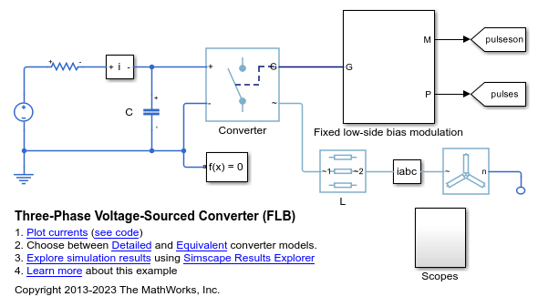
三相电压源型转换器 (FLB)
此示例展示了如何对使用固定低侧偏置调制 (FLB) 调制的三相电压源型转换器进行建模。这种调制方案在任何给定时间都有一相不进行脉冲调制,从而最大限度减少了转换器中的开关动作。其代价是,在给定的可接受谐波水平下需要更窄的脉冲。该模型可用于帮助选择合适的 L、C 和脉冲调制方案参数值。

三相电压源型转换器 (SPWM)
此示例展示了如何对使用正弦脉冲宽度调制 (SPWM) 的三相电压源型转换器进行建模。此调制方案将参考正弦波与更高频率的重复三角波进行比较以生成脉冲。该模型可用于帮助选择合适的 L、C 和脉冲调制方案参数值。

基于晶闸管的整流器
此示例展示了一个基于晶闸管的整流器。

图腾柱 PFC
此示例展示了如何控制图腾柱功率因子校正 (PFC) 电路中的整流电压。MOSFET Q1 和 Q2 构成 50 kHz 快速开关桥臂。MOSFET Q3 和 Q4 构成线频慢速开关桥臂。Control 子系统采用基于 PI 的级联控制结构。Scopes 子系统包含示波器,可用于查看仿真结果。

十二脉冲晶闸管整流器
此示例展示了如何控制十二脉冲晶闸管整流器。两个晶闸管转换器连接到输入端的一个星型-三角型-星型变压器。Thyristor 12-Pulse Generator 模块为两个转换器生成栅极信号。

维也纳整流器控制
此示例展示了如何控制维也纳整流器。Vienna rectifier 子系统由三相桥臂组成。每个桥臂包含一个功率开关和六个功率二极管。Control 子系统采用空间矢量调制为维也纳整流器实现闭环控制策略。总仿真时间为 0.1 秒。在时间 0.1 秒时,维也纳整流器开始运行。在时间 0.4 秒和 0.6 秒时,DC 侧负载上升。

三相并网整流器控制
此示例展示了如何使用并网整流器控制 DC 链路电压。Rectifier control 子系统采用基于 PI 的级联控制结构。Scopes 子系统包含示波器,可用于查看仿真结果。如果您拥有 HDL Coder™ 许可证,您可以使用 Simscape™ HDL Workflow Advisor 为 FPGA 生成 VHDL 代码。

三相并网逆变器
此示例展示了如何控制并网逆变器系统中的电压。Voltage regulator 子系统实现基于 PI 的控制策略。三相逆变器通过 Circuit Breaker 连接到电网。Circuit Breaker 在仿真开始时处于断开状态,以便进行同步。在 0.15 秒时,Circuit Breaker 闭合,逆变器连接到电网。Scopes 子系统包含示波器,可用于查看仿真结果。逆变器采用 IGBT 实现。为加快仿真速度或进行实时部署,可以用平均开关代替 IGBT。这样,栅极信号可以在指定时间段内取平均值,或者用调制波形代替。
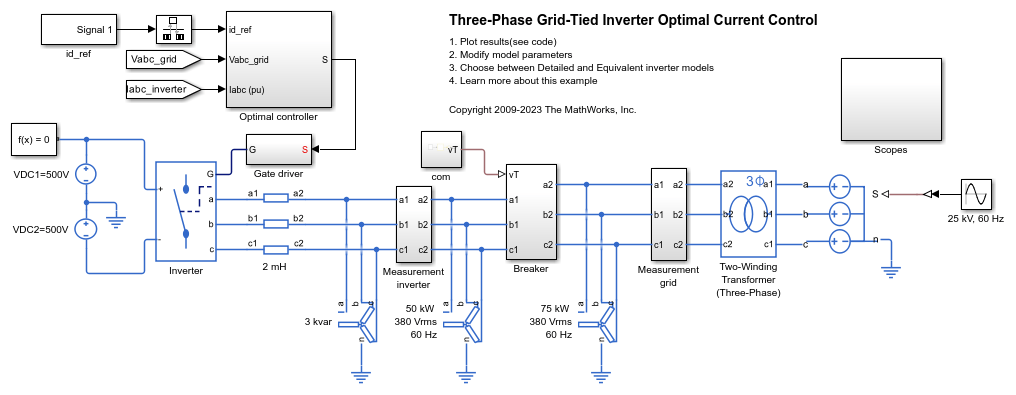
三相并网逆变器最优电流控制
此示例展示了如何控制并网逆变器系统中的电流。Optimal controller 子系统实现一种基于观测器的线性二次调节器策略。为了确保稳态误差为零,此示例使用观测器作为积分作用的替代方法。SPST 开关将三相逆变器连接到电网。这些开关在仿真开始时处于断开状态,以便进行同步。在 0.15 秒时,逆变器连接到电网。随后在 0.2 秒时,逆变器增加提供给电网的有功功率。Scopes 子系统包含示波器,可用于查看仿真结果。逆变器采用 Ideal Semiconductor Switch 模块实现。如果您拥有 HDL Coder™ 许可证,您可以使用 Simscape™ HDL Workflow Advisor 为 FPGA 生成 VHDL 代码。

三相逆变器电压控制
此示例展示了如何控制三相逆变器系统中的电压。逆变器采用 IGBT 实现。为加快仿真速度或进行实时部署,可以用平均开关代替 IGBT。这样,栅极信号可以在指定时间段内取平均值,或者用调制波形代替。

Three-Phase Matrix Converter with Venturini Modulation
Use Venturini modulation techniques to compute the duty cycles and logic statements of a three-phase matrix converter that drives a static load. The control subsystem implements three different modulation algorithms: Venturini modulation, third harmonic enhanced Venturini modulation, and third harmonic injection Venturini modulation with unity input displacement factor. The maximum voltage transfer ratio between input and output depends on the modulation technique and it is equal to either q=0.5 or q=0.866. The Scope blocks show the voltages and currents V_ABC, V_abc, I_ABC, and I_abc, where _UPPERCASE is used for inputs and _LOWERCASE for outputs.
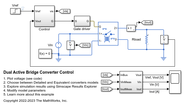
双有源桥式控制
此示例展示了如何控制双有源桥式 DC-DC 转换器的输出电压。每个开关在其开关周期内的导通时间占 50%。相移控制器在输出桥中引入可变相移并控制输出电压。在整个仿真过程中,输入电压和系统负载保持恒定。总仿真时间 (t) 为 0.25 秒。在 t = 0.15 秒时,电压参考值发生变化。
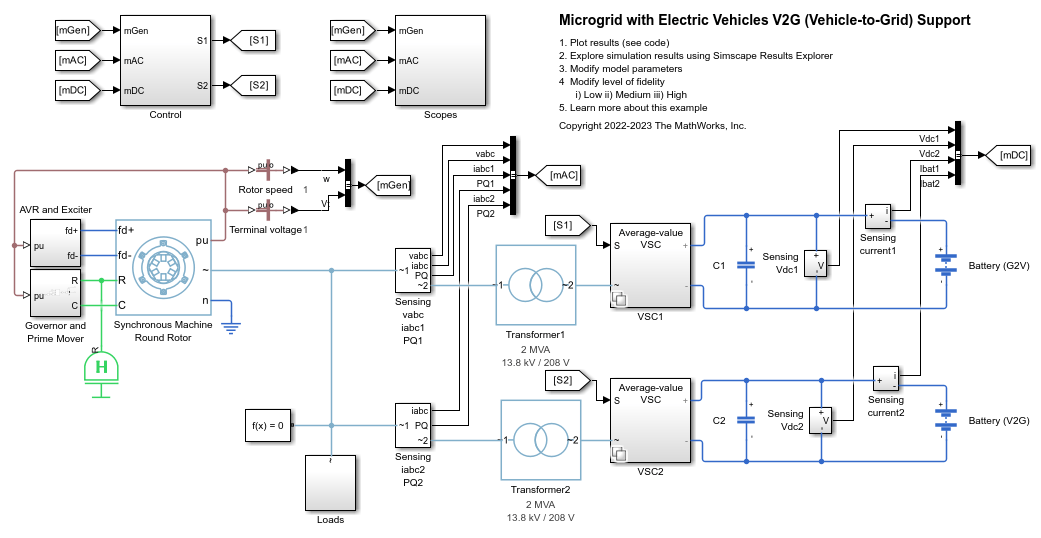
Microgrid with Electric Vehicles V2G (Vehicle-to-Grid) Support
Model a microgrid and how to regulate its frequency by using vehicle-to-grid (V2G) support from electric vehicles (EVs).
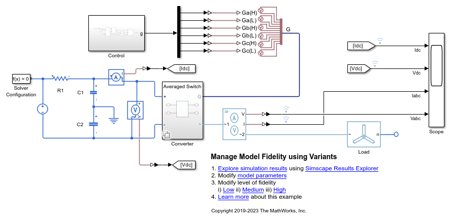
Manage Model Fidelity Using Variants
Compare and contrast modeling different fidelity levels by using variants. The controller model uses a Variant Source block configured in Expression mode. The plant model uses a Variant Subsystem.

Test Harness to Generate High-Power IGBT Device Characteristics
Provides test harness for estimating switching loss for different parameters of a N-Channel IGBT block.
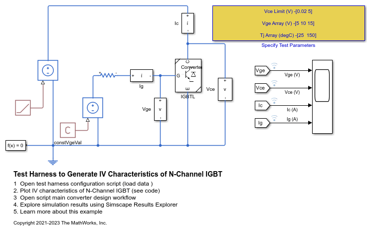
Test Harness to Generate IV Characteristics of N-Channel IGBT
Provides test harness for estimating current-voltage characteristics of a N-Channel IGBT.

Three-Phase High-Power Converter Design and Analysis Workflow
The main steps involved in designing a high-power converter. High power converters are important building blocks for future electric mobility and microgrid solutions. To design a cost effective, lightweight, efficient converter, you must perform detailed analysis of different converter design options and deployment scenarios. This example helps you to simulate the steady state, transient electrical, and thermal characteristics of a three-phase two-level converter that uses Insulated-Gate Bipolar Transistor (IGBT) devices.
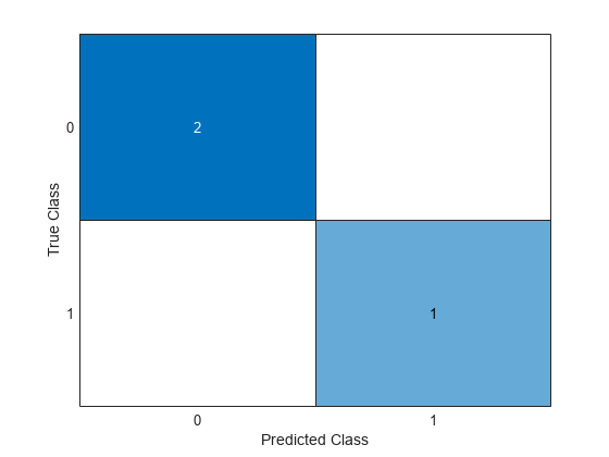
Fault Detection of Electric Vehicle Charger
Analyzes the fault of an electric vehicle (EV) charger using Simscape™ Electrical™ to model the grid, the converter, and its control unit. The reliability of these chargers is an important factor in their adoption. In this example, you use measurements from the grid and the DC side of the converter to detect a gate driver fault in the converter. To analyze and detect a fault, first you generate synthetic data for different conditions with and without faults. Then you use this data to train a classification algorithm using the 分类学习器 (Statistics and Machine Learning Toolbox). Finally, you use the trained model to identify or detect faults in any phase and to generate the code for deployment on hardware. You can extend this model for other system level variations or noises by having a much larger and comprehensive training dataset.

Optimize Liquid Cooling System of Inverter
Analyze the performance of a liquid cooling system for a three-phase inverter. To find the steady-state temperatures and losses, you first run detailed and reduced order models (ROM). Then you compute the optimal size of the heatsink that maximizes the inverter efficiency and minimizes the lifetime cost.

High-Voltage, Direct-Current Transmission Using Voltage Source Converters
Models a high-voltage, direct-current (HVDC) transmission system using voltage source converters (VSCs).