Bridge Cycloconverter Voltage Controller (Three-Phase)
RMS Voltage PI control for three-phase bridge cycloconverters
Libraries:
Simscape /
Electrical /
Control /
Converter Control
Description
The Bridge Cycloconverter Voltage Controller (Three-Phase) block implements a PI-based root-mean-square (RMS) voltage controller for three-phase bridge cycloconverters.
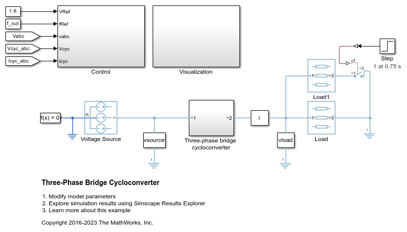
To convert a three-phase signal directly from a higher frequency to a lower frequency, use this block with a three-phase bridge cycloconverter. Refer to Three-Phase Bridge Cycloconverter for an example of such a conversion.
Operating Principle
The controller regulates the cycloconverter line-to-neutral RMS voltage to a given value and a given electrical frequency. The structure of the cycloconverter controller is illustrated in this diagram.

In the diagram:
The controller integrates the desired output frequency fref to produce the reference electrical angle θe_ref.
The Signal Conditioning block filters the cycloconverter line-to-neutral voltage vcyc and current icyc to produce the per-unit RMS voltage vrms_cyc and smoothed current signal icyc_lpf.
The PI Controller generates a reference phase voltage in the q-axis from the error between the desired output RMS voltage Vref and vrms_cyc.
The Inverse Park Transform block converts the reference phase voltage in dq0-coordinates to a phase voltage vabc_ref in abc-coordinates.
The Sinusoidal Power Measurement (PLL, Three-Phase) block estimates the phase angle θ of the input voltage signal vabc.
The Modulator and Bank Selector blocks create the 36 pulses to drive the cycloconverter using the reference phase voltage vabc_ref, estimated phase angle θ, and filtered cycloconverter current icyc_lpf. To generate the firing angles, the controller uses the cosine wave crossing method.
This diagram shows the signal conditioning logic.

In the diagram:
The Park Transform blocks convert the measured cycloconverter voltage vcyc and current icyc into d- and q-axis components (vd,vq,id,iq) using the reference electrical angle θe_ref.
The Low-Pass Filter (LPF) blocks remove the high-frequency noise from each of the d- and q-axis voltage and currents to produce the filtered components (vd_lpf, vq_lpf, id_lpf, iq_lpf).
The block calculates the cycloconverter per-unit RMS voltage vrms_cyc by taking the squared sum of the dq components, dividing by , and finally converting from SI to per-unit representation.
The Inverse Park Transform converts the dq filtered current back to the abc-axis and outputs it as icyc_lpf.
The cycloconverter reference line-to-neutral rms voltage output is given in per-unit representation.
Visualization
The block outputs a bus containing six signals for visualization:
The estimated phase angle θ of the input voltage signal vabc
The desired RMS voltage Vref of the output signal
The reference phase voltages vabc_ref of the desired output signal
The filtered line-to-neutral cycloconverter RMS voltage vrms_cyc
The filtered cycloconverter phase currents icyc_lpf
The filtered cycloconverter phase voltages vcyc_lpf
Examples
Ports
Input
Output
Parameters
References
[1] Chen, H., M. H. Johnson, and D. C. Aliprantis. "Low-frequency AC transmission for offshore wind power." IEEE Transactions on Power Delivery. Vol. 28, Number 4, 2013, pp. 2236–2244.
Extended Capabilities
Version History
Introduced in R2017b

