Park Transform
实现 abc 到 dq0 的变换

库:
Simscape /
Electrical /
Control /
Mathematical Transforms
描述
Park Transform 模块将 abc 参考系中三相系统的时域分量转换为旋转参考系中的直轴、交轴和零轴分量。通过实现一种不变版本的帕克变换,此模块可以保持与 abc 参考系中的系统功率相等的有功功率和无功功率。对于平衡系统,零轴分量等于零。
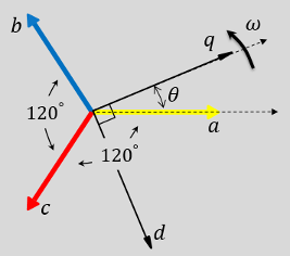
您可以将此模块配置为在时间 t = 0 时,使三相系统的 a 轴与旋转参考系的 d 轴或 q 轴对齐。下面的图显示了 abc 参考系和 dq0 旋转参考系中定子绕组磁轴的方向,其中:
a 轴和 q 轴初始对齐。
a 轴和 d 轴初始对齐。
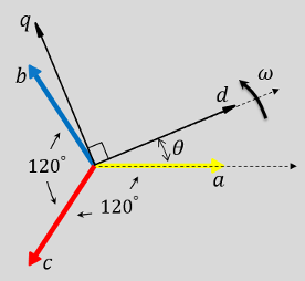
在这两种情况下,角度 θ = ωt,其中:
θ 是 a 轴与 q 轴之间的角度(对于 q 轴对齐),或是 a 轴与 d 轴之间的角度(对于 d 轴对齐)。
ω 是 d-q 参考系的转速。
t 是从初始对齐算起的时间,以秒为单位。
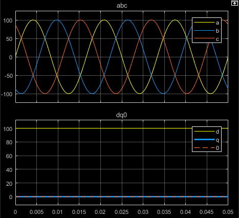
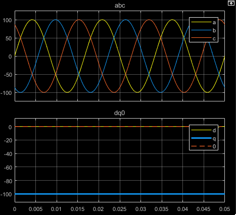
下面的图显示了等效平衡 abc 和 dq0 各分量在以下情况下的时间响应:
a 相向量与 q 轴对齐
a 相向量与 d 轴对齐
方程
Park Transform 模块按如下方程实现 a 相与 q 轴对齐的变换:
其中:
a、b 和 c 是 abc 参考系中三相系统的分量。
d 和 q 是旋转参考系中双轴系统的分量。
0 是静止参考系中双轴系统的零轴分量。
对于功率不变的 a 相与 q 轴对齐,此模块使用以下方程实现变换:
对于 a 相与 d 轴对齐,此模块使用以下方程实现变换:
此模块按如下方程实现功率不变的 a 相与 d 轴对齐的变换:
示例
电动发动机测功机
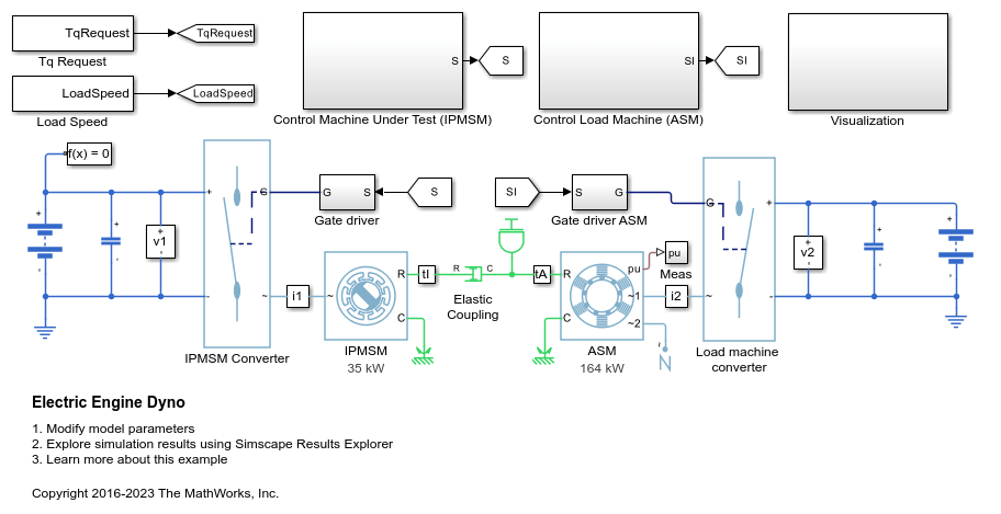
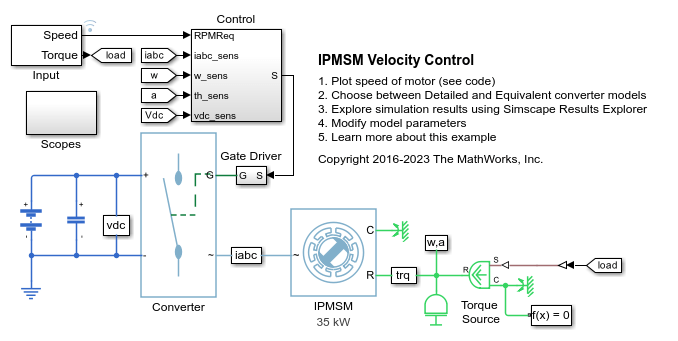
此示例展示了如何对电动汽车测功机测试进行建模。测试环境包含一台异步电机 (ASM) 和一台内置式永磁同步电机 (IPMSM),它们通过机械轴背靠背连接。这两台电机均由高压电池通过受控三相转换器供电。由功率为 164 kW 的 ASM 产生负载转矩。功率为 35 kW 的 IPMSM 是在测电机。Control Machine Under Test (IPMSM) 子系统控制 IPMSM 的转矩。该控制器包括基于 PI 的多速率控制结构。开环转矩控制的速率低于闭环电流控制的速率。控制器的任务调度以 Stateflow® 状态机的形式实现。Control Load Machine (ASM) 子系统使用单速率来控制 ASM 的转速。Visualization 子系统包含示波器,可用于查看仿真结果。
48V 起动发电机中的能量平衡
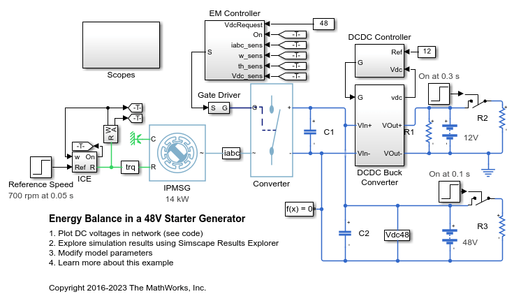
An interior permanent magnet synchronous machine (IPMSM) used as a starter/generator in a simplified 48V automotive system. The system contains a 48V electric network and a 12V electric network. The internal combustion engine (ICE) is represented by basic mechanical blocks. The IPMSM operates as a motor until the ICE reaches the idle speed and then it operates as a generator. The IPMSM supplies power to the 48V network, which contains the R3 power consumer. The 48V network supplies power to the 12V network which has two consumers: R1 and R2. The total simulation time (t) is 0.5 seconds. At t = 0.05 seconds, the ICE turns on. At t = 0.1 seconds, R3 switches on. At t = 0.3 seconds, R2 switches on and increases the load on the 12V electric network. The EM Controller subsystem includes a multi-rate PI-based cascade control structure which has an outer voltage-control loop and two inner current-control loops. The task scheduling in the Control subsystem is implemented as a Stateflow® state machine. The DCDC Controller subsystem implements a simple PI controller for the DC-DC Buck converter, which feeds the 12V network. The Scopes subsystem contains scopes that allow you to see the simulation results.
HESM 转矩控制
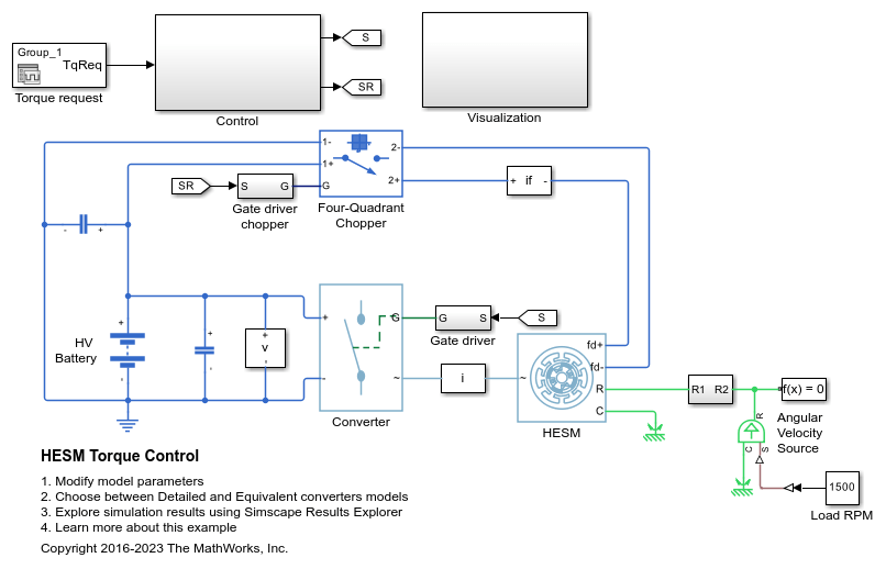
此示例展示了如何控制基于混合励磁同步电机 (HESM) 的电力牵引驱动装置中的转矩。HESM 由永磁体和励磁绕组励磁。高压电池通过受控三相转换器为 SM 定子绕组供电,通过受控四象限斩波器为 SM 转子绕组供电。理想角速度源提供负载。Control 子系统使用开环方法控制转矩,并使用闭环方法控制电流。在每个采样时刻,转矩请求都会转换为相关的参考电流。电流控制基于 PI。仿真在电机模式和发电机模式下都使用了多个转矩阶跃。Visualization 子系统包含示波器,可用于查看仿真结果。
HESM 速度控制
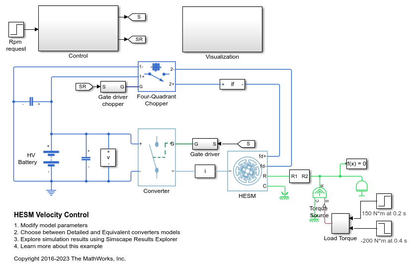
此示例展示了如何控制基于混合励磁同步电机 (HESM) 的电力牵引驱动装置中的转子角转速。HESM 由永磁体和励磁绕组励磁。高压电池通过受控三相转换器为 HESM 定子绕组供电,通过受控四象限斩波器为 HESM 转子绕组供电。理想转矩源提供负载。Control 子系统包含基于 PI 的多速率级联控制结构。控制结构具有一个外层角速度控制环和三个内层电流控制环。Visualization 子系统包含示波器,可用于查看仿真结果。
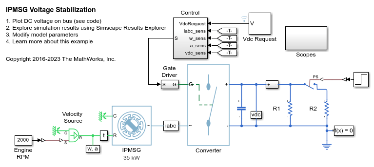
IPMSG 电压稳定
Control an Interior Permanent Magnet Synchronous Generator (IPMSG) based low voltage generator system for a hybrid electric vehicle (HEV). The Control subsystem includes a multi-rate PI-based cascade control structure which has an outer voltage-control loop and two inner current-control loops. The task scheduling in the Control subsystem is implemented as a Stateflow® state machine. The Scopes subsystem contains scopes that allow you to see the simulation results. An ideal angular velocity source, which represents a combustion engine, drives the IPMSG. The IPMSG supplies low-voltage power to loads R1 and R2. At t = 0.4 seconds, the switch closes, increasing the load.
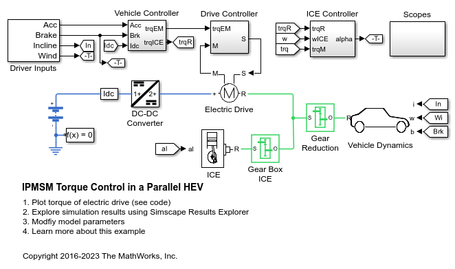
并联 HEV 中的 IPMSM 转矩控制
A simplified parallel hybrid electric vehicle (HEV). An interior permanent magnet synchronous machine (IPMSM) and an internal combustion engine (ICE) provide the vehicle propulsion. The IPMSM operates in both motoring and generating modes. The vehicle transmission and differential are implemented using a fixed-ratio gear-reduction model. The Vehicle Controller subsystem converts the driver inputs into torque commands. The vehicle control strategy is implemented as a Stateflow® state machine. The ICE Controller subsystem controls the torque of the combustion engine. The Drive Controller subsystem controls the torque of the IPMSM. The Scopes subsystem contains scopes that allow you to see the simulation results.
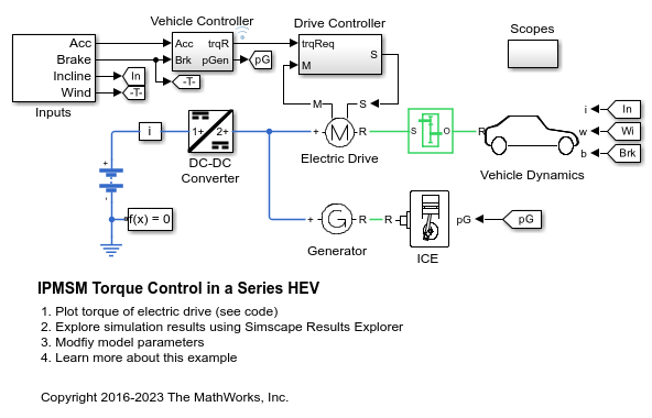
串联 HEV 中的 IPMSM 转矩控制
An interior permanent magnet synchronous machine (IPMSM) propelling a simplified series hybrid electric vehicle (HEV). An ideal DCDC converter, connected to a high-voltage battery, feeds the IPMSM through a controlled three-phase converter. A combustion engine driven generator charges the high-voltage battery. The vehicle transmission and differential are implemented using a fixed-ratio gear-reduction model. The Vehicle Controller subsystem converts the driver inputs into relevant commands for the IPMSM and generator. The Drive Controller subsystem controls the torque of the IPMSM. The controller includes a multi-rate PI-based control structure. The rate of the open-loop torque control is slower than the rate of the closed-loop current control. The task scheduling for the controller is implemented as a Stateflow® state machine. The Scopes subsystem contains scopes that allow you to see the simulation results.

串并联 HEV 中的 IPMSM 转矩控制
A simplified series-parallel hybrid electric vehicle (HEV). An interior permanent magnet synchronous machine (IPMSM) and an internal combustion engine (ICE) provide the vehicle propulsion. The ICE also uses electric generator to recharge the high-voltage battery during driving. The vehicle transmission and differential are implemented using a fixed-ratio gear-reduction model. The Vehicle Controller subsystem converts the driver inputs into torque commands. The vehicle control strategy is implemented as a Stateflow® state machine. The ICE Controller subsystem controls the torque of the combustion engine. The Generator Controller subsystem controls the torque of the electric generator. The Drive Controller subsystem controls the torque of the IPMSM. The Scopes subsystem contains scopes that allow you to see the simulation results.
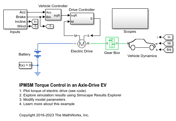
轴驱动 HEV 中的 IPMSM 转矩控制
此示例展示了一个内置式永磁同步电机 (IPMSM) 驱动简化版轴驱动电动汽车。高压电池通过受控三相转换器为 IPMSM 供电。IPMSM 以电机模式和发电模式运行。车辆变速器和差速器采用固定速比齿轮减速模型实现。Vehicle Controller 子系统将驾驶员的驾驶动作转换为相关的转矩命令。Drive Controller 子系统控制 IPMSM 的转矩。该控制器包括基于 PI 的多速率控制结构。开环转矩控制的速率低于闭环电流控制的速率。控制器的任务调度以 Stateflow® 状态机的形式实现。Scopes 子系统包含示波器,可用于查看仿真结果。
IPMSM 速度控制
此示例展示了如何控制基于内置式永磁同步电机 (IPMSM) 的汽车电力牵引驱动装置中的转子角转速。高压电池通过受控三相转换器为 IPMSM 供电。IPMSM 根据负载以电机模式和发电模式运行。理想转矩源提供负载。Scopes 子系统包含示波器,可用于查看仿真结果。Control 子系统包含基于 PI 的多速率级联控制结构,该结构具有一个外层角速度控制环和两个内层电流控制环。Control 子系统中的任务调度以 Stateflow® 状态机的形式实现。在时长一秒的仿真过程中,角速度需求为 0 rpm、500 rpm、2000 rpm,然后是 3000 rpm。

SM 转矩控制
此示例展示了如何控制基于同步电机 (SM) 的电力牵引驱动装置中的转矩。高压电池通过受控三相转换器为 SM 定子绕组供电,通过受控四象限斩波器为 SM 转子绕组供电。理想角速度源提供负载。Control 子系统使用开环方法控制转矩,并使用闭环方法控制电流。在每个采样时刻,转矩请求都会转换为相关的参考电流。电流控制基于 PI。仿真在电机模式和发电机模式下都使用了多个转矩阶跃。任务调度以 Stateflow® 状态机的形式实现。Visualization 子系统包含示波器,可用于查看仿真结果。
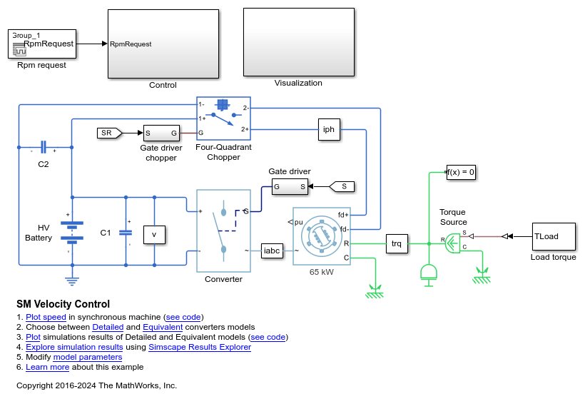
SM 速度控制
此示例展示了如何控制基于同步电机 (SM) 的电力牵引驱动装置中的转子角转速。高压电池通过受控三相转换器为 SM 定子绕组供电,通过受控四象限斩波器为 SM 转子绕组供电。理想转矩源提供负载。Control 子系统包含基于 PI 的多速率级联控制结构,该结构具有一个外层角速度控制环和三个内层电流控制环。Control 子系统中的任务调度以 Stateflow® 状态机的形式实现。Visualization 子系统包含示波器,可用于查看仿真结果。
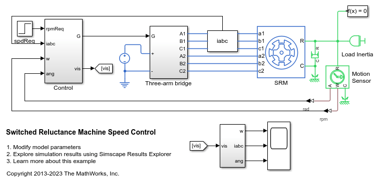
开关磁阻电机转速控制
此示例展示了如何控制基于开关磁阻电机 (SRM) 的电力驱动装置中的转子转速。DC 电压源通过受控三臂桥为 SRM 供电。为了实现正向和反向旋转,此示例使用转速误差来调整转换器的导通和关断角度。
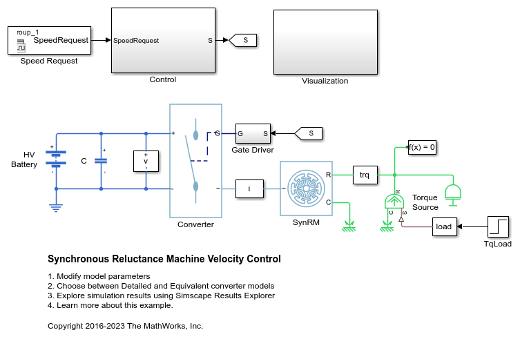
同步磁阻电机速度控制
此示例展示了如何控制基于同步磁阻电机 (SynRM) 的电力驱动装置中的转子角速度。高压电池通过受控三相转换器为 SynRM 供电。理想转矩源提供负载。Control 子系统包含基于 PI 的多速率级联控制结构。控制结构具有一个外层角速度控制环和两个内层电流控制环。Visualization 子系统包含示波器,可用于查看仿真结果。
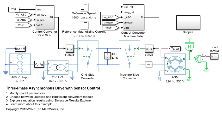
带传感器控制的三相异步驱动
此示例展示了如何使用带传感器转子磁场定向控制来控制和分析异步电机 (ASM) 的运行。该模型展示了主电路,以及包含控制、测量和示波器的三个附加子系统。Controls 子系统包含两个控制器:一个用于电网侧转换器 (AC/DC),另一个用于电机侧转换器 (DC/AC)。Scopes 子系统包含两个示波器:一个用于电网侧转换器,另一个用于 ASM。执行该模型时,频谱分析仪会打开并显示 A 相电源电流的频率数据。
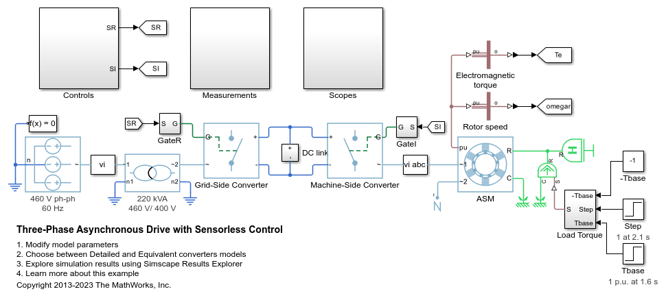
无传感器控制的三相异步驱动
此示例展示了如何使用无传感器转子磁场定向控制来控制和分析异步电机 (ASM) 的运行。该模型展示了主电路,以及包含控制、测量和示波器的三个附加子系统。Controls 子系统包含两个控制器:一个用于电网侧转换器 (AC/DC),另一个用于电机侧转换器 (DC/AC)。Scopes 子系统包含两个示波器:一个用于电网侧转换器,另一个用于 ASM。执行该模型时,频谱分析仪会打开并显示 A 相电源电流的频率数据。
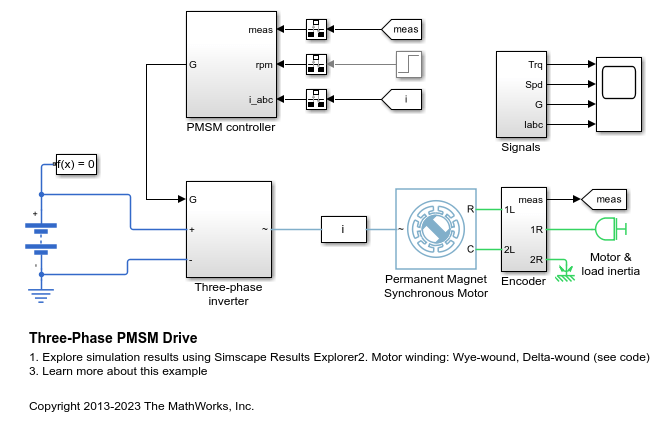
三相 PMSM 驱动
此示例展示了一个采用星型绕组和三角型绕组配置的永磁同步电机 (PMSM),以及一个适用于典型混合动力车辆的逆变器。该逆变器直接连接到车辆电池,但您也可以在两者之间实现一个 DC-DC 转换器阶段。使用该模型,通过选择架构和增益来设计 PMSM 控制器,从而实现期望的性能。为了检查 IGBT 开通和关断时序,请使用更详细的 N-Channel IGBT 模块替换 IGBT 器件。对于整车建模,请使用 Motor & Drive (System Level) 模块,以基于能量的模型来抽象 PMSM、逆变器和控制器。
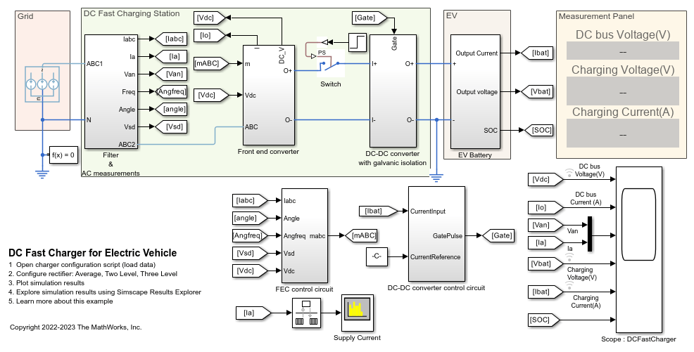
电动汽车 DC 快速充电站
此示例对与电动汽车 (EV) 电池包连接的 DC 快速充电站进行建模。
端口
输入
输出
参数
参考
[1] Krause, P., O. Wasynczuk, S. D. Sudhoff, and S. Pekarek. Analysis of Electric Machinery and Drive Systems. Piscatawy, NJ: Wiley-IEEE Press, 2013.
扩展功能
版本历史记录
在 R2017b 中推出