验证机器冷却系统架构的需求
此示例展示了如何验证机器冷却架构模型系统设计的需求。在本示例中,您将学习如何:
编写序列图来规划利益相关者的需求,并根据代表功能工作流的状态图进行仿真。
实现需求表,以正式证明需求的一致性和完整性。
通过围绕组件创建测试框架来执行单元测试,以验证系统需求。
查看可追溯性图,该图可追溯数字线程从实现到利益相关者的需求。
在此示例中,使用机器冷却系统来演示工作流。机器冷却系统在机器过热时对机器进行冷却。如果冷却无效,机器冷却系统将关闭机器以防止损坏。
打开机器冷却工程示例
要开始,请打开此示例的工程。
openProject("scMachineCoolingExample");要在工程中使用自定义功能,请加载 Simulink® 自定义设置。
sl_refresh_customizations;
定义需求
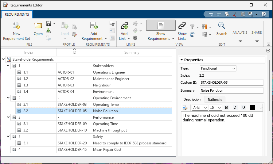
您可以使用 Requirements Toolbox™ 在了解利益相关者的需求后,定义利益相关者的需求。利益相关者的需求是描述与系统交互的参与者需要的高级需求,包括环境、性能、安全和维修问题。在 需求编辑器 (Requirements Toolbox) 中,使用需求视图来编写这些需求。在工程中,在工程快捷方式选项卡中,点击工程快捷方式 1. Stakeholder Requirements。需求编辑器显示了此示例工程的利益相关者需求。
例如,Noise Pollution 利益相关者需求表明,运行噪音不应超过 100 分贝。以下步骤验证了 Operating Temp 的需求。这些利益相关者的需求转化为系统需求,您可以使用这些需求来验证系统设计是否符合利益相关者的需求。
使用架构模型表示系统场景
使用 System Composer™ 编写用于逻辑分析的架构模型。该模型描述了机器的运行环境、冷却系统的逻辑行为以及机器冷却系统为降低高温而采取的措施。在工程中,在工程快捷方式选项卡中,点击工程快捷方式 2. Cooling Scenarios。System Composer 显示机器冷却场景作为输入、行为和动作。
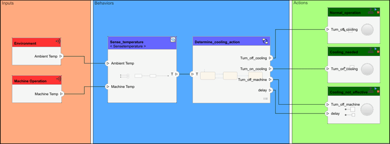
在此架构模型中,环境温度和机器温度被输入到 Sense_temperature 组件,该组件将温度转换为输入到 Determine_cooling_action 组件,该组件决定下一步操作。操作场景包括:
继续正常运行,由
Normal_operation组件表示。冷却机器,由组件
Cooling_needed代表。出现错误并关闭机器,由组件
Cooling_not_effective表示。
要查看哪些需求与哪个系统组件相关联,您可以进入“需求透视”。从 System Composer 模型导航到 App>需求管理器。
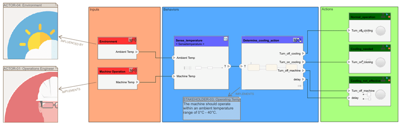
环境参与者需求与机器冷却架构模型中的 Environment 组件相关联。Operations Engineer 演员需求与 Machine Operation 组件相关联。Determine_cooling_action 组件链接到 Operating Temp 利益相关者需求。链接到 Determine_cooling_action 组件的状态图行为通过设计验证了 Operating Temp 的需求。
使用序列图描述系统行为
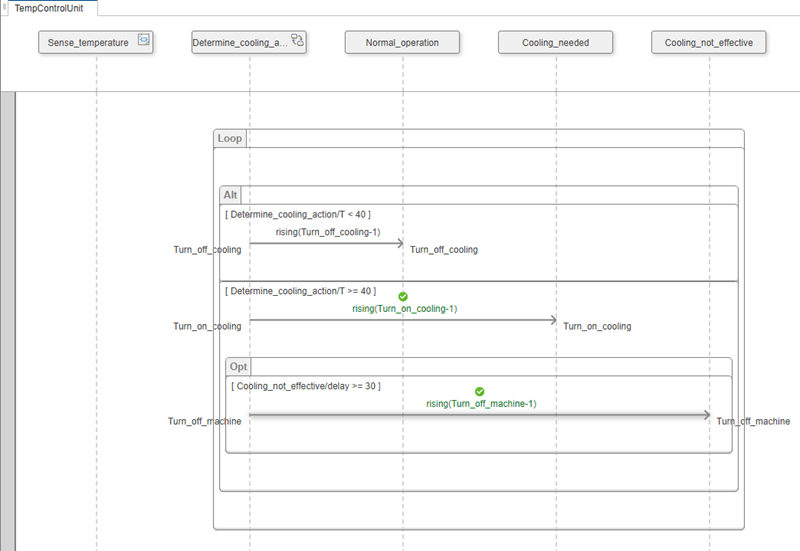
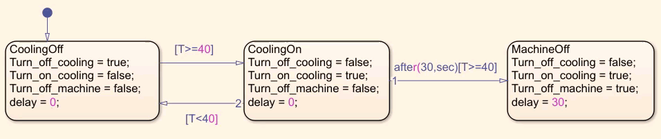
序列图作为描述性模型。描述性模型是系统的图形化规范,用于向利益相关者传达不同的操作场景。您可以在 System Composer 中使用序列图来评估架构模型中组件之间的交互。在工程中,在工程快捷方式选项卡中,点击工程快捷方式 3. Test Sequence Diagram。序列图 TempControlUnit 显示了机器冷却系统的操作场景。
根据序列图,温度升至 40 度以上,冷却系统启动,然后由于冷却无效,机器关闭。有关创建序列图的更多信息,请参阅使用序列图描述系统行为。
序列图使用状态图来跟踪使用 Stateflow® 组件实现的操作场景。
有关在 System Composer 中创建状态图的更多信息,请参阅使用 Stateflow 图实现组件行为。
使用需求表分析需求
为了保持设计中需求的完整性和一致性,您可以使用 Requirements Table (Requirements Toolbox) 模块来分析它们。确定问题后,您可以调整需求。在工程中,在工程快捷方式选项卡中,点击工程快捷方式 4. Requirements Table。该模型显示了带有机器冷却输入的 Requirements Table 模块。
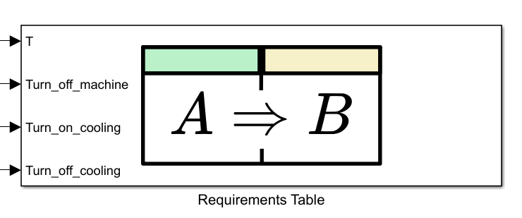
使用 Simulink Design Verifier™,您可以在需求表中查看需求覆盖范围的正式描述。打开 Requirements Table (Requirements Toolbox) 模块。在工具栏上,选择表>分析表以确定需求表是否一致,或查看操作以恢复一致性。
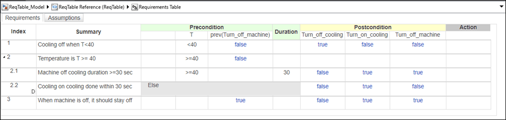
此示例的需求是一致的,因为它们之间不存在冲突。需求是完整的,因为它们没有缺少任何功能。有关详细信息,请参阅识别不一致和不完整的正式需求集 (Requirements Toolbox)。
使用单元测试验证需求
您可以将需求作为单元测试的一部分,通过使用 Simulink Test™ 来验证功能模型在设计流程的不同阶段是否满足需求。在工程中,在工程快捷方式选项卡中,点击工程快捷方式 5. Validate Cooling。Simulink 测试管理器 (Simulink Test)随即打开。Test cooling behavior 测试套件包含两个场景:
Cooling not effective机器过热,冷却系统无法有效降低温度,因此机器必须自动关闭。
Cooling effective机器过热,但冷却系统运行正常,机器可继续正常运行。
对于每个场景,测试框架围绕在测系统,通过一组受控的输入和输出将系统隔离。要从 Simulink Test 管理器打开测试框架,请点击打开指定的测试框架 ![]() 按钮。
按钮。
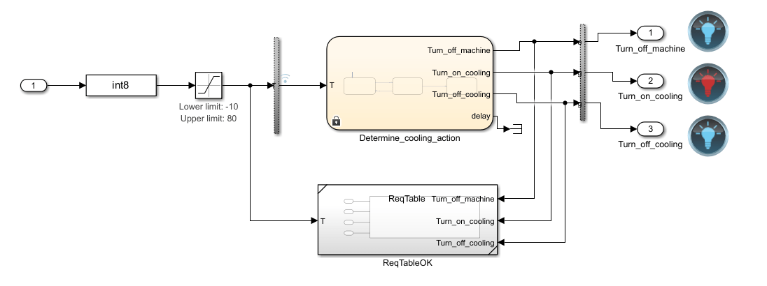
为了定义模型参数,Simulink Test Manager 在每次测试开始时,使用工作区变量加载每个场景的输入部分。点击运行进行测试。Simulink Test 管理器将结果显示在结果选项卡中。
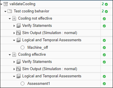
所有测试均通过,以绿色勾号表示。有关 System Composer 中测试框架的更多信息,请参阅验证和确认需求。
使用可追溯性图创建数字线程
数字线程可帮助您了解通过需求分析、验证和系统设计如何验证特定利益相关者的需求。您可以使用 Requirements Toolbox 中的可追溯性图创建数字线程。要查看利益相关者的需求,在工程中,在工程快捷方式选项卡中,点击工程快捷方式 1. Stakeholder Requirements。在需求编辑器中,从 2.1 Operating Temp 需求集中选择 StakeholderRequirements 需求。在工具栏上,选择分析>可追溯性图,然后查看所选需求周围的路径。
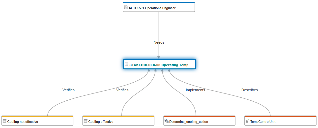
Operations Engineer 演员需要满足 Operating Temp 的需求。Cooling not effective 和 Cooling effective 测试用例验证了 Operating Temp 的需求。Determine_cooling_action 状态图实现了 Operating Temp 的需求。TempControlUnit 序列图描述了 Operating Temp 需求。
随着系统设计的进展,跟踪数字线程以显示需求验证,可以提高对有效系统行为的信心。有关可追溯性图的更多信息,请参阅使用可追溯性图可视化链接 (Requirements Toolbox)。
另请参阅
模块
- Requirements Table (Requirements Toolbox)
工具
- 需求编辑器 (Requirements Toolbox) | 需求管理器 (Requirements Toolbox) | 架构视图库 | Simulink 测试管理器 (Simulink Test)
函数
slreq.editor(Requirements Toolbox) |sl_refresh_customizations