targetPoses
Find positions, orientations, velocities, angular velocities, and accelerations of targets relative to ego UAV platform
Since R2023b
Description
poses = targetPoses(scene,platform)
Examples
Create a default UAV scenario.
scene = uavScenario;
Create an ego UAV platform. Set the ego UAV to hover 20 meters above the reference location with an angular velocity of 5 deg/s around the z- axis.
egoPlatform = uavPlatform("egoUAV",scene,InitialPosition=[0 0 -20], ...
    InitialAngularVelocity=[0 0 deg2rad(5)],ReferenceFrame="NED");
Update the ego UAV platform mesh, and set the color.
C = colororder;
updateMesh(egoPlatform,"quadrotor",{10},C(5,:),eul2tform([0 0 pi]))
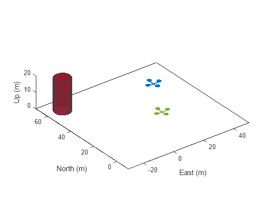
Create a target UAV platform. Set the target UAV to hover 40 meters north and 25 meters east of the reference location at an altitude of 10 meters.
targetPlatform = uavPlatform("targetUAV",scene,InitialPosition=[40 25 -10]);Use updateMesh to set the UAV platform mesh to the quadrotor model, and set the color.
updateMesh(targetPlatform,"quadrotor",{10},C(1,:),eul2tform([0 0 pi]))Add a static mesh to the scene 60 meters north and 20 meters west of the reference location. Set the color of the static mesh.
addMesh(scene,"cylinder",{[-20 60 5],[0 20]},C(7,:))Add a ground plane and show the scenario.
patch([-30 -30 50 50],[-10 70 70 -10],[0 0 0 0],[1 1 1]);
hold on
show3D(scene);
xlim([-30 50])
ylim([-10 70])
zlim([0 20])
Set up the simulation.
setup(scene);
Obtain the poses of the target UAV and mesh.
poses = targetPoses(scene,egoPlatform);
Extract the pose of the target UAV. The pose shows that the target UAV is 40 meters further north, 25 meters further east, and 10 meters below the ego UAV position. The target UAV also has a velocity of –3.49 m/s in the y- direction and an angular velocity of –5 deg/s on the z- axis relative to the ego UAV.
TargetUAVPose = poses(1)
TargetUAVPose = struct with fields:
         PlatformID: 2
            ClassID: 0
           Position: [40.0000 25.0000 10.0000]
        Orientation: [1×1 quaternion]
           Velocity: [2.1817 -3.4907 8.5496e-16]
    AngularVelocity: [0 -1.2246e-15 -5]
       Acceleration: [0 0 0]
Extract the pose of the static mesh. The pose shows that, relative to the ego UAV position, the static mesh is 60 meters further north, 20 meters further west, and 10 meters below the ego UAV position. The static mesh also has a velocity of –5.23 m/s in the y-direction and an angular velocity of –5 deg/s on the z- axis relative to the ego UAV.
StaticMeshPose = poses(2)
StaticMeshPose = struct with fields:
         PlatformID: 3
            ClassID: 0
           Position: [60.0000 -20.0000 10.0000]
        Orientation: [1×1 quaternion]
           Velocity: [-1.7453 -5.2360 1.2824e-15]
    AngularVelocity: [0 -1.2246e-15 -5]
       Acceleration: [0 0 0]
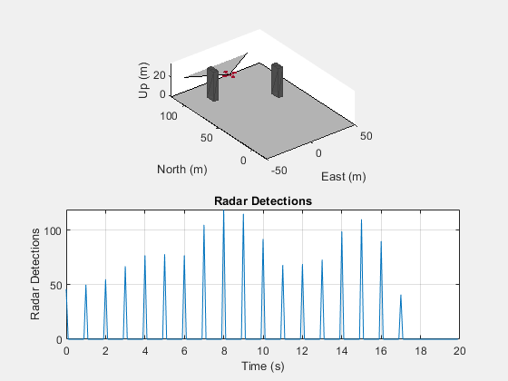
Create a UAV scenario with an update rate of 10 Hz and simulation stop time of 20 seconds. Add polygon meshes to the scenario, to serve as radar targets.
scene = uavScenario(UpdateRate=10,StopTime=20);
geometry1 = {[-25 100; -20 100; -20 90; -25 90] [0 30]};
geometry2 = {[25 70; 30 70; 30 60; 25 60] [0 30]};
color = [0.3 0.3 0.3];
addMesh(scene,"polygon",geometry1,color)
addMesh(scene,"polygon",geometry2,color)
Create an ego UAV platform plat with an initial position 15 meters above the reference location. Create a mesh for the ego UAV platform, and specify the x-positions of the ego UAV waypoints.
plat = uavPlatform("UAV",scene,InitialPosition=[0 0 -15]);
updateMesh(plat,"quadrotor",{15},[0.6350 0.0780 0.1840],eul2tform([0 0 pi]))
xpos = linspace(0,100,200);
Obtain the bounding box dimensions and RCS signatures of the target meshes.
targetProfile.Dimensions = boundingBoxDimensions(scene.Meshes{1,1});
targetProfile.Signatures = {exampleHelperMesh2RCS(scene.Meshes{1,1})};
Add a radar to the scenario by using the radarDataGenerator System object™. Based on the Echodyne EchoFlight UAV radar [1], set the radar configuration as:
Frequency — 24.55 GHz
Field of view — 120azimuth, 80 elevation
Resolution — 2 azimuth, 6 elevation
Full scan rate — 1 Hz
Sensitivity — 0 dBsm at 200 m
Additionally, set the TargetReportFormat property of the radarDataGenerator object to "Detections" so that the radar outputs multiple detections per target.
radarSensor = radarDataGenerator("no scanning",SensorIndex=1, ...
   FieldOfView=[120 80], ...
   UpdateRate=1, ...
   MountingAngles=[0 0 0], ...
   MountingLocation=[0 0 0], ...
   HasElevation=true, ...
   ElevationResolution=6, ...
   AzimuthResolution=2, ...
   RangeResolution=4, ...
   RangeLimits=[0 200], ...
   ReferenceRange=200, ...
   CenterFrequency=24.55e9, ...
   Bandwidth=200e6, ...
   TargetReportFormat="Detections", ...
   DetectionCoordinates="Sensor rectangular", ...
   HasFalseAlarms=false, ...
   FalseAlarmRate=1e-7, ...
   Profiles=targetProfile);
Create a figure with two subplots. In the first subplot, show the UAV scenario and display the radar field of view from the ego UAV platform body frame. In the second subplot, create an empty plot to capture the number of detections generated by the radar at each simulation timestep.
% Create the first subplot.
subplot(2,1,1)

% Show the UAV scenario.
[ax,plotFrames] = show3D(scene);
xlim([-50 50])
ylim([-20 120])
zlim([0 35])
x = [-50 -50 50 50];
y = [-25 120 120 -25];

% Create the ground plane.
patch(x,y,[.7 .7 .7])

% Show the radar field of view.
radarDirection = hgtransform("Parent",plotFrames.UAV.BodyFrame,"Matrix",eye(4));
coverageAngles = linspace(-radarSensor.FieldOfView(1)/360*pi,radarSensor.FieldOfView(1)/360*pi,128);
patch("XData",[0 radarSensor.RangeLimits(2)*cos(coverageAngles) 0], ...
    "YData",[0 radarSensor.RangeLimits(2)*sin(coverageAngles) 0], ...
    FaceAlpha=0.3,Parent=radarDirection);

% Create the second subplot.
subplot(2,1,2)

% Create an empty plot to show the number of radar reports.
numReportsArray = NaN([1 200]);
simTimeArray = NaN([1 200]);
p = plot(simTimeArray,numReportsArray);
p.XDataSource = "simTimeArray";
p.YDataSource = "numReportsArray";
xlabel("Time (s)")
ylabel("Radar Detections")
title("Radar Detections")
grid on
set(gcf,visible="off")
Set up the simulation, then iterate through the positions. In each step, generate the radar detections, update the radar detections subplot, show the scene, advance the simulation time, and move the ego UAV platform to the next waypoint.
set(gcf,visible="on")

setup(scene)
for idx = 0:size(xpos,2)-1
    [reports,numReports] = radarSensor(targetPoses(scene,plat),scene.CurrentTime);
    numReportsArray(idx+1) = numReports;
    simTimeArray(idx+1) = scene.CurrentTime;

    % Use fast update to move platform visualization frames.
    show3D(scene,FastUpdate=true,Parent=ax);

    % Refresh radar detections plot data and visualize.
    refreshdata
    drawnow limitrate

    % Advance scene simulation time and move the ego UAV platform.
    advance(scene);
    move(plat,[xpos(idx+1) 0 -15 0 0 0 0 0 0 1 0 0 0 0 0 0])
end

The radar outputs multiple unclustered detections per target. To cluster the detections using the density-based spatial clustering of applications (DBSCAN) with noise algorithm, see clusterDBSCAN (Radar Toolbox).
Supporting Functions
The exampleHelperMesh2RCS function estimates the RCS signatures of a target mesh by adding together the RCS signature of each face of the target, as viewed from the radar location.
function sig  = exampleHelperMesh2RCS(M)
    % List the constants obtained from the radar specifications.
    freq = 24.55e9;
    az = -180:4:180;
    el = -90:4:90;
    nrcs = -20;
    az = az(:).';
    el = el(:);

    % Calculate the center and vertices of the mesh.
    center = (min(M.Vertices,[],1) + max(M.Vertices,[],1))/2;
    vertices = M.Vertices - center;

    v1 = vertices(M.Faces(:,1),:);
    v2 = vertices(M.Faces(:,2),:);
    v3 = vertices(M.Faces(:,3),:);

    % Calculate the width of the mesh.
    w1 = v2 - v1;
    w2 = v3 - v1;

    n = [w1(:,2).*w2(:,3) - w2(:,2).*w1(:,3), ...
        w2(:,1).*w1(:,3) - w1(:,1).*w2(:,3), ...
        w1(:,1).*w2(:,2) - w2(:,1).*w1(:,2)];

    a = sqrt(sum(n.^2,2));
    n = n./a;
    a = a/2;
    c = (v1 + v2 + v3)/3;

    farFieldRange = 2e2;
    lambda = 299792458/freq;

    % Create an array of zeros for the RCS pattern.
    rcs = zeros(numel(el),numel(az));

    % Populate the RCS pattern array by adding together the RCS pattern of each face of the mesh.
    for azind = 1:numel(az)
        for elind = 1:numel(el)

            [src(1),src(2),src(3)] = sph2cart(az(azind)*pi/180,el(elind)*pi/180,farFieldRange);

            los = src - c;
            R = sqrt(sum(los.^2,2));
            los = los./R;

            A = a.*sum(n.*los,2)/lambda;
            I = find(A > 0);
            A = A(I);
            R = R(I);

            rcs(elind,azind) = sum(A.*exp(1i*2*pi/lambda*R));

        end
    end

    rcs = 10^(nrcs/10)*abs(rcs);
    rcs(rcs==0) = eps;

    % Use rcsSignature to create a RCS signature object.
    if numel(el) == 1
        sig = rcsSignature(Azimuth=az,Elevation=[el; el],Pattern=10*log10(rcs));
    else
        sig = rcsSignature(Azimuth=az,Elevation=el,Pattern=10*log10(rcs));
    end
end
The boundingBoxDimensions function computes the cuboid dimensions of a target mesh for the radar model.
function D = boundingBoxDimensions(mesh)
    D.Length = max(mesh.Vertices(:,1)) - min(mesh.Vertices(:,1));
    D.Width  = max(mesh.Vertices(:,2)) - min(mesh.Vertices(:,2));
    D.Height = max(mesh.Vertices(:,3)) - min(mesh.Vertices(:,3));
    D.OriginOffset = [0 0 0];
end
References
Airborne UAV Radar - Echodyne.” Accessed June 21, 2023. https://www.echodyne.com/applications/aam/airborne-uav-radar/
Input Arguments
UAV scenario, specified as a uavScenario
object.
Ego UAV platform, specified as uavPlatform
object.
Output Arguments
Poses of all targets relative to the ego UAV, returned as a structure or a N-element
array of structures. N is the total number of targets in the scenario, excluding the ego
UAV platform. This output does not include the pose of the ego UAV platform
platform. Each pose consists of the position, velocity,
acceleration, and orientation of all targets in ego UAV platform body
coordinates.
The first M structures in the array contain the poses of target
platforms, where M is equal to the size of scene.Platforms-1. The remaining structures in the array
contain the poses of the static meshes in scene.
Each structure has these fields.
| Field | Description |
|---|---|
PlatformID | Unique target identifier, returned as a positive integer. The identifiers for the first M - 1 structures
in the array are the indices of the corresponding target platforms in the
The identifiers for each of the remaining structures are
M + N, where N is the index of the
corresponding target mesh in the |
ClassID | Classification identifier of target, returned as a nonnegative
integer. The default value of |
Position | Position of the target in ego UAV body coordinate, specified as a real-valued vector of the form [x y z]. This field has no default value. Units are in meters. |
Velocity | Velocity of the target in ego UAV body coordinates, returned as a real-valued vector of the form [vx vy vz]. This field has no default value. Units are in m/s. |
Acceleration | Acceleration of the target in ego UAV body coordinates, returned as a real-valued vector of the form [ax ay az]. Units are in m/s2. The default value is [0 0 0]. |
Orientation | Orientation of the target with respect to the ego UAV body frame, returned as a scalar quaternion. Orientation defines the frame rotation from the ego UAV body frame to the target body frame. |
AngularVelocity | Angular velocity (ω) of the target in the positive x-, y-, and z- directions of the ego UAV body coordinate, returned as a real-valued vector of the form [ωx ωy ωz]. Units are in deg/s. |
More About
When using targetPoses, you must specify one UAV platform as the
observer of all other UAV platforms and static meshes. The observer UAV platform is the
ego UAV. The ego UAV platform observes all other UAV and meshes,
which are the targets. The position and orientation of the ego UAV
defines the origin and orientation of the ego UAV body frame.
Version History
Introduced in R2023b
MATLAB Command
You clicked a link that corresponds to this MATLAB command:
Run the command by entering it in the MATLAB Command Window. Web browsers do not support MATLAB commands.
选择网站
选择网站以获取翻译的可用内容,以及查看当地活动和优惠。根据您的位置,我们建议您选择:。
您也可以从以下列表中选择网站:
如何获得最佳网站性能
选择中国网站(中文或英文)以获得最佳网站性能。其他 MathWorks 国家/地区网站并未针对您所在位置的访问进行优化。
美洲
- América Latina (Español)
- Canada (English)
- United States (English)
欧洲
- Belgium (English)
- Denmark (English)
- Deutschland (Deutsch)
- España (Español)
- Finland (English)
- France (Français)
- Ireland (English)
- Italia (Italiano)
- Luxembourg (English)
- Netherlands (English)
- Norway (English)
- Österreich (Deutsch)
- Portugal (English)
- Sweden (English)
- Switzerland
- United Kingdom (English)