Design and Tune Controller for VTOL UAV
This series of examples shows you how to design and tune a vertical takeoff and landing (VTOL) UAV controller by using a reference application template. This example series accesses and modifies the reference application template using a Simulink project. For more information about MATLAB Projects, see Create Projects.
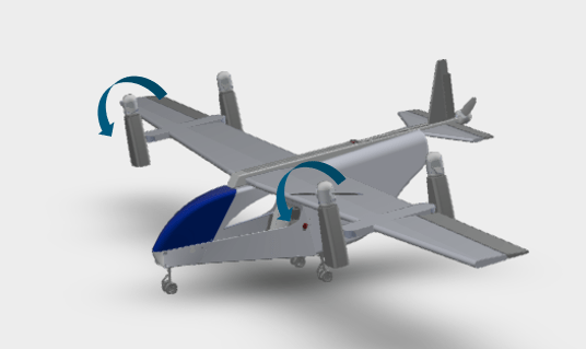
The reference application models the VTOL UAV in a tilt-rotor configuration. In this configuration, the VTOL UAV operates two fixed rear rotors, two tilting front rotors, and a wing. This configuration enables the VTOL UAV to take off and land vertically without a runway, similarly to a multicopter, while attaining a relatively high cruising speed by transitioning to a fixed-wing configuration.
VTOL UAV Control Design Steps
This example series shows you how to tune a VTOL UAV controller for all phases of mission in an urban environment, such as hover flight, fixed-wing flight, and the transition between these two phases. This series also shows you how to verify your controller by deploying it onto a PX4® Autopilot for hardware-in-the-loop (HITL) simulation, and how to visualize the simulation in 3D environment using Unreal Engine®
The example series consists of these steps.
Open VTOL UAV Project and Model
The VTOLRefApp.prj Simulink project file contains the reference application, which consists of a Simulink model and its supporting files, as well as the additional riles and project shortcuts that this example series uses. Open the project file by running this code.
% Open the Simulink project.
prj = openProject("VTOLApp/VTOLRefApp.prj");
Open the VTOLTiltrotor.slx Simulink model.
open_system("VTOLTiltrotor")
The VTOLTiltrotor Simulink model contains these main subsystems, which you can customize in accordance with your design:
Ground Control Station— Commands the VTOL UAV to execute a set of maneuvers to complete a mission.Autopilot— VTOL UAV flight controller, which contains theLow level controllerandGuidance Test Benchsubsystems. TheGuidance test benchsubsystem contains a high-level controller that calculates the setpoint of the low level controller during various flight modes, such as takeoff, forward transition, waypoint navigation, orbit, backward transition, and landing. TheGuidance test benchsubsystem also determines the conditions in which the modes change during the mission.Manual Control Dashboard— Use this subsystem to manually control the VTOL UAV. Before using this subsystem, you must enable the manual control mode of the test bench.Digital Twin— VTOL UAV plant model. This subsystem contains the dynamic, aerodynamic, and propulsion models of the VTOL UAV.Visualization— Visualize the VTOL UAV flight.
Simulate Your First VTOL UAV Flight
First, set up the VTOL UAV plant and enable the hover configuration. On the Project tab of the MATLAB Toolstrip, in the Shortcuts section, select Set up Plant. Alternatively, you can use the setupPlant helper function.
setupPlant
Initialized VTOL model.
Enabled hover configuration.
Enabled hover guidance mission.
To enable manual control, select the Manual Mode shortcut from the Hover section, or use the setupHoverManual helper function.
setupHoverManual
Enabled hover manual testbench mode.
Run the VTOLTiltrotor.slx model, and navigate to VTOLTiltrotor/Manual Control Dashboard subsystem.

Adjust the Hover Commands sliders to manually select the setpoints for the X, Y, and altitude values. Observe that the VTOL UAV follows the setpoints that you select.

This example series enables you to use a hover guidance mission to verify your hover controller gains, which ensures that the VTOL UAV is able to follow more aggressive setpoints while operating in an urban environment. During the guidance mission, the Guidance Test Bench subsystem calculates the hover controller setpoints based on the mission and the current state of the UAV.
Before resuming to other examples in this example series, you must close the VTOLRefApp.prj Simulink project by running this command in the Command Window:
close(prj)
For an example of how to verify the ability of the UAV to follow a more complex trajectory, and how to tune the controller gains to improve the tracking performance in hover mode, see the Tune Control Design for VTOL UAV in Hover Configuration example.