Tune Control Design for VTOL UAV in Transition
This example shows how to tune your VTOL aircraft control parameters during the Transition Flight Regime. During the transition, the aircraft changes from vertical to horizontal flight, and vice versa, which poses a challenge to stability and control due to significant changes in flight dynamics. Before deploying the controller to flight control hardware, you can tune the control parameters to verify the chosen parameters before flight test.
Getting Started
To open the example livescript and directory which contains the Simulink project file, first run openExample('uav/TuneControlDesignForUAVInTransitionExample') in the command window.
You must open the VTOLRefApp.prj project file to access the Simulink model, supporting files, and project shorcuts that this example uses.
% Open the Simulink project after running openExample('uav/TuneControlDesignForUAVInTransitionExample')
prj = openProject("VTOLApp/VTOLRefApp.prj");
This example uses MATLAB Project shortcuts. Use the highlighted project shortcuts for setting up the transition configuration. You can use the other project shortcuts for tuning the hover, fixed-wing configurations, and setting up the photorealistic city mission. To see these shortcuts, you must open and view the Project Shortcuts tab.

Click the Getting Started button in the project shortcuts to set up the aircraft plant model and base controller.
setupPlant;
Initialized VTOL model.
Enabled hover configuration.
Enabled hover guidance mission.
Set Up Transition Experiment
First, obtain the hover flight state.
FSState=flightState.Hover;
To configure the UAV to hover configuration, use the exampleHelperGetInitialConfiguration function with the flight state that you have obtained. In this configuration, the UAV hovers and the rotors point upwards.
[vIni,tiltIni]=exampleHelperGetInitialConfiguration(FSState);
Load the UAV controller gains from the previous hover and fixed-wing mode tuning examples.
% Load controller gains for hover mode
load tunedHoverGains_BW50;
% Load controller gains for fixed-wing mode
load tunedFixedWingGains_BW10.mat
Set Up Guidance Test Bench for Transition Mission.
The controller must be be able to safely control the VTOL UAV during transition phase from hover mode to fixed-wing mode, and vice versa. To study the sensitivity of various UAV transition parameters, leverage the guidance testbench
To set up a short transition mission consisting of hover, transition, and fixed-wing flight, click Guidance Mode shortcut, or run the setupHoverGuidanceMission helper function.
setupTransitionSensitivityMission;
Enabled transition sensitivity mission.
Analyze Sensitivity of Transition to Parameters
In the previous examples, you have tuned the control design for hover and fixed wing configurations. The aircraft switches between these two controller modes based on the transition parameters. During the transition, the parameters in VTOLTiltrotor/Autopilot/Tilt Scheduler will be tuned in order to facilitate both forward and backward transition maneuvers.
The transition parameters are chosen specific to this tiltrotor control design. However, you can use the mission test bench approach for studying transition sensitivity of a different control design. The automated mission setup can also be used to do a parameter study for a different control structure.
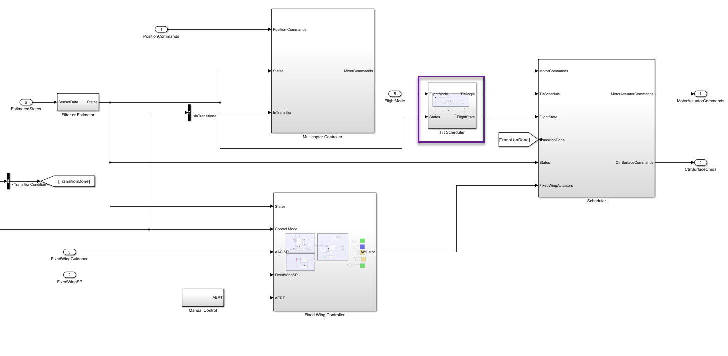
During forward transition, the following parameters impact the behavior of the current tiltrotor control design:
Tilt Schedule Rate — The rate in which the front rotors tilts forward.
Critical Tilt Angle — Specifies the angle of tilt that once reached, the front rotors tilt forward as fast as physically possible.
Wind down — Rate at which Back rotors gradually wind down until a complete stop.
Once a given velocity is reached, the UAV fully transitions to fixed wing flight. In the following subsections, study the impact of each effect on transition.
Effect of Tilt Schedule Rate on Transition
Control the tilt schedule rate by changing the TiltScheduleRate parameter. TiltScheduleRate affets the Tilt Scheduler within the VTOLTiltrotor/Autopilot/Tilt Scheduler subsystem.
tiltRateParam = getEntry(dDataSectObj,'TiltScheduleRate');Use the sim command to run the model with a transition rate of 15, 30, and 45 degrees per second. Store the output of each simulation run in variables outTR15, outTR30, and outTR45, respectively.
% Transition rate set to 15 deg/sec.
setValue(tiltRateParam,15*pi/180)
% Run Simulation
outTR15=sim(mdl);
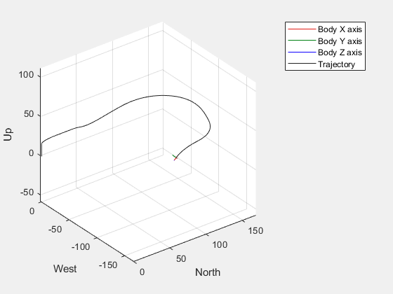
% Transition rate set to 30 deg/sec.
setValue(tiltRateParam,30*pi/180)
% Run Simulation
outTR30=sim(mdl);
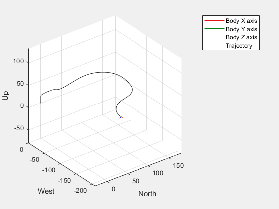
% Transition rate set to 45 deg/sec.
setValue(tiltRateParam,45*pi/180)
% Run Simulation
outTR45=sim(mdl);
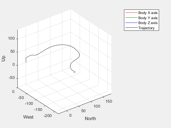
Plot the simulation outputs to compare the altitude, pitch, tilt, and airspeed at each tilt schedule rate by using the exampleHelperPlotTransitionResults function.
tLayout=tiledlayout(4,1);
exampleHelperPlotTransitionResults(tLayout,outTR15);
exampleHelperPlotTransitionResults(tLayout,outTR30);
exampleHelperPlotTransitionResults(tLayout,outTR45);
leg=legend({'Tilt Rate 15 deg/sec','Tilt Rate 30 deg/sec','Tilt Rate 45 deg/sec'});
leg.Layout.Tile='north';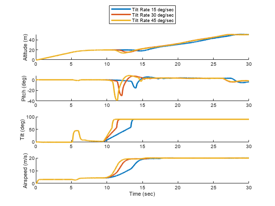
Observe that a rate of 15 degrees per second resulted in low oscillations in pitch and without excessive time spent exceeding the transition velocity of 14 meters per second. Therefore, set the transition schedule rate to 15 degrees per second.
setValue(tiltRateParam,15*pi/180);
Effect of Critical Tilt Angle on Transition
Prior to reaching critical angle, the rotor tilt rate is slower and defined by TiltScheduleRate. Once the critical tilt angle is reached, the UAV tilts its rotors forward as fast as the servo dynamics allow.
Control the critical angle by changing the CriticalTiltAngle parameter.
criticalAngleParam = getEntry(dDataSectObj,'CriticalTiltAngle');Use the sim command to run the model with a critical tilt angle of 90, 60, and 30 degrees. Store the output of each simulation run in variables outTC90, outTC60, and outTC30, respectively.
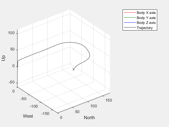
% Critical tilt set to 90 degrees (gradual tilt during the entire transition phase).
setValue(criticalAngleParam,pi/2)
% Run simulation
outTC90=sim(mdl);
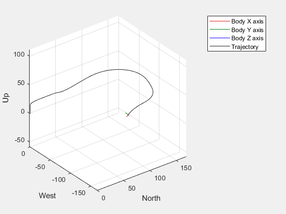
% Critical tilt set to 60 degrees.
setValue(criticalAngleParam,pi/3)
% Run simulation
outTC60=sim(mdl);
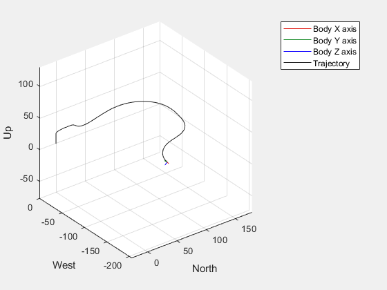
% Critical tilt set to 30 degrees.
setValue(criticalAngleParam,pi/6)
% Run simulation
outTC30=sim(mdl);
Plot results for comparison.
tLayout=tiledlayout(4,1);
exampleHelperPlotTransitionResults(tLayout,outTC90);
exampleHelperPlotTransitionResults(tLayout,outTC60);
exampleHelperPlotTransitionResults(tLayout,outTC30);
leg=legend({'Critical Tilt Angle=90 deg','Critical Tilt Angle=60 deg','Critical Tilt Angle=30 deg'});
leg.Layout.Tile='north';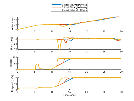
As the UAV approaches the fixed wing mode, the back rotors have more influence on pitch as the front rotor vector points forward. If the transition to fixed wing mode is too slow, this can lead to changes in pitch that need correction.
Observe that 60 degrees of critical angle leads to low oscillation in pitch close to transition without causing a significant reduction in airspeed. Thus 60 degrees (pi/3 radian) is chosen as the critical angle.
setValue(criticalAngleParam,pi/3)
Effect of Wind Down Rate on Transition
WindDownRate, specified in , is the rate at which the back rotors reduce their speed during transition.
A high wind down rate would cause the back rotors lose authority to balance pitch of the UAV during transition to fixed wing flight. Conversly, lower wind down rate will increase the authority of the back motor during the transition at the expense of increased battery consumption.
To open the example that examines the effect of wind down rate, run exampleHelperWinddownStudy in the terminal.
Back Transition
During back transition, the UAV tilts the front rotors slightly backward to slow down. Once the UAV's speed is less than the transition threshold, the UAV switches to hover mode and move horizontally to the landing position before vertically land.
The back transition is primarily controlled by setting the proportional gain for the forward velocity control. To examine the back transition, open 'VTOLTiltrotor/Autopilot/TiltScheduler/Back Transition Scheduler.

Simulate Full Mission with Transition
Set up and simulate the transition guidance mission with the tuned transition parameters.
setupTransitionGuidanceMission;
Enabled transition guidance mission.
sim(mdl);
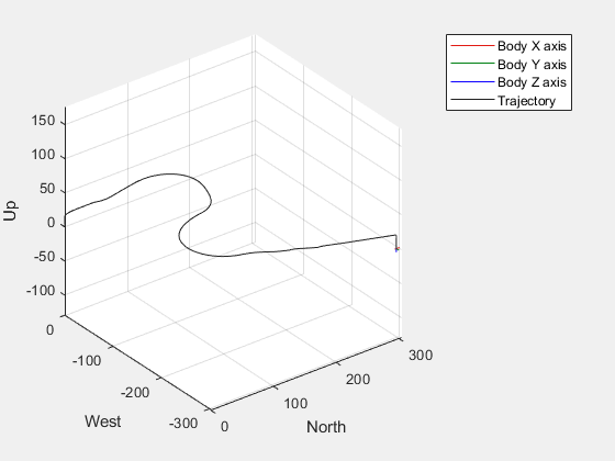
You can add GPS, IMU, and airspeed sensors to the system and test how the UAV performs over the mission with sensors in the loop. The sensor subsystem can be found in 'VTOLTiltrotor/Digital Twin/Variant Subsystem/Sensors/SensorData. To run the simulation with sensors, run this code section, then run the model.
% Set up manual mode.
setupHoverManual
Enabled hover manual testbench mode.
% Set sensor flag (0/1 to disable/enable sensor).
SensorType=1;

% Set sensor delay rate.
SensorDelayRate=0.001;
Before resuming to other examples in this example series, you must close the VTOLRefApp.prj Simulink project by running this command in the Command Window:
close(prj)
References
[1] N., Pavan. (2020). Design of Tiltrotor VTOL and Development of Simulink Environment for Flight Simulations.
[2] Mathur, Akshay & Atkins, Ella. (2021). Design, Modeling and Hybrid Control of a QuadPlane.
[3] Ducard, Guillaume Jacques Joseph and Minh-Duc Hua (2014). Modeling of an unmanned hybrid aerial vehicle.