Camera Calibration Using Custom Planar Calibration Patterns
This example shows how to create a custom calibration pattern detector and how to calibrate a camera both programmatically and by using the Camera Calibrator app.
Overview
The Camera Calibrator and Stereo Camera Calibrator apps natively support the use of the following patterns to calibrate single and stereo cameras: Checkerboard, Circle Grid, ChArUco board, and AprilGrid. To calibrate cameras using calibration images containing any of these patterns, refer to Using the Single Camera Calibrator App. Additionally, the apps provide the ability to add a custom pattern detector for calibrating cameras using images of a planar calibration pattern that is not natively supported by the apps.
For illustration purposes, this example uses a custom calibration pattern made up of AprilTags to collect camera calibration images and uses the readAprilTag function to detect and localize AprilTags in a calibration pattern. If you are calibrating using AprilGrid patterns based on AprilTags, you can use the detectAprilGrid function for programmatic calibration or the Using the Single Camera Calibrator App for the app-based calibration.
In this example, you first generate a custom calibration pattern using AprilTags to collect camera calibration images. You then implement the custom pattern detector to calibrate a camera programmatically and by using the Camera Calibrator app.
Camera Calibration Using Functional Interface
Step 1: Generate the calibration pattern
Download and prepare tag images
Pre-generated tags for all the supported families can be downloaded from here using a web browser or by running the following code:
downloadURL  = "https://github.com/AprilRobotics/apriltag-imgs/archive/master.zip";
dataFolder   = fullfile(tempdir,"apriltag-imgs",filesep);
options      = weboptions('Timeout', Inf);
zipFileName  = fullfile(dataFolder,"apriltag-imgs-master.zip");
folderExists = exist(dataFolder,"dir");

% Create a folder in a temporary directory to save the downloaded file.
if ~folderExists
    mkdir(dataFolder);
    disp("Downloading apriltag-imgs-master.zip (60.1 MB)...")
    websave(zipFileName,downloadURL,options);

    % Extract contents of the downloaded file.
    disp("Extracting apriltag-imgs-master.zip...")
    unzip(zipFileName,dataFolder);
end
Downloading apriltag-imgs-master.zip (60.1 MB)...
Extracting apriltag-imgs-master.zip...
The helperGenerateAprilTagPattern function at the end of the example can be used to generate a calibration target using the tag images for a specific arrangement of tags. The pattern image is contained in calibPattern, which can be used to print the pattern (from MATLAB®). The example uses the tag36h11 family, which provides a reasonable tradeoff between detection performance and robustness to false-positive detections.
% Set the properties of the calibration pattern.
tagArrangement = [5,8];
tagFamily = "tag36h11";

% Generate the calibration pattern using AprilTags.
tagImageFolder = fullfile(dataFolder,"apriltag-imgs-master",tagFamily);
imdsTags = imageDatastore(tagImageFolder);
calibPattern = helperGenerateAprilTagPattern(imdsTags,tagArrangement,tagFamily);

Using the readAprilTag function on this pattern results in detections with the corner locations of the individual tags grouped together. The helperAprilTagToCheckerLocations function can be used to convert this arrangement to a column-major arrangement, such as a checkerboard.
% Read and localize the tags in the calibration pattern.
[tagIds, tagLocs] = readAprilTag(calibPattern,tagFamily);

% Sort the tags based on their ID values.
[~, sortIdx] = sort(tagIds);
tagLocs = tagLocs(:,:,sortIdx);

% Reshape the tag corner locations into an M-by-2 array.
tagLocs = reshape(permute(tagLocs,[1,3,2]),[],2);

% Convert the AprilTag corner locations to checkerboard corner locations.
checkerIdx = helperAprilTagToCheckerLocations(tagArrangement);
imagePoints = tagLocs(checkerIdx(:),:);

% Display corner locations.
figure; imshow(calibPattern); hold on
plot(imagePoints(:,1),imagePoints(:,2),"ro-",MarkerSize=15)

Prepare images for calibration
A few points to note while preparing images for calibration:
While the pattern is printed on a paper in this example, consider printing it on a surface that remains flat, and is not subject to deformations due to moisture, etc.
Since the calibration procedure assumes that the pattern is planar, any imperfections in the pattern (e.g. an uneven surface) can reduce the accuracy of the calibration.
The calibration procedure requires at least 2 images of the pattern but using between 10 and 20 images produces more accurate results.
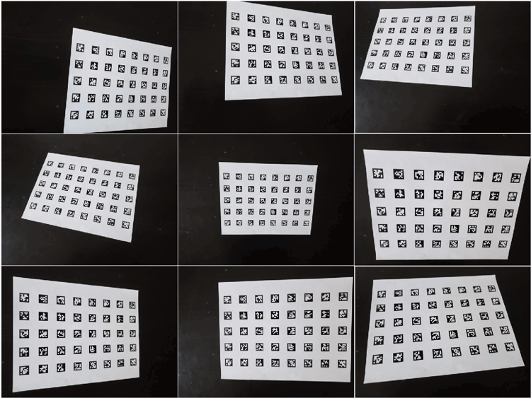
Capture a variety of images of the pattern such that the pattern fills most of the image, thus covering the entire field of view. For example, to best capture the lens distortion, have images of the pattern at all edges of the image frame.
Make sure the pattern is completely visible in the captured images since images with partially visible patterns will be rejected.
For more information on preparing images of the calibration pattern, see Prepare Camera and Capture Images for Camera Calibration.
Step 2: Detect and localize the AprilTags
The helperDetectAprilTagCorners function, included at the end of the example, is used to detect, and localize the tags from the captured images and arrange them in a checkerboard fashion to be used as key points in the calibration procedure.
% Create an imageDatastore object to store the captured images.
imdsCalib = imageDatastore("aprilTagCalibImages/");

% Detect the calibration pattern from the images.
[imagePoints,boardSize] = helperDetectAprilTagCorners(imdsCalib,tagArrangement,tagFamily);
Step 3: Generate world points for the calibration pattern
The generated AprilTag pattern is such that the tags are in a checkerboard fashion, and so the world coordinates for the corresponding image coordinates determined above (in imagePoints) can be obtained using the generateCheckerboardPoints function.
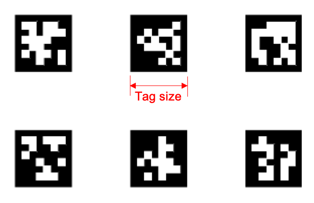
Here, the size of the square is replaced by the size of the tag, and the size of the board is obtained from the previous step. Measure the tag size between the outer black edges of one side of the tag.
% Generate world point coordinates for the pattern.
tagSize = 16; % in millimeters
worldPoints = patternWorldPoints("checkerboard",boardSize, tagSize);
Step 4: Estimate camera parameters
With the image and world point correspondences, estimate the camera parameters using the estimateCameraParameters function.
% Determine the size of the images.
I = readimage(imdsCalib,1);
imageSize = size(I,1:2);

% Estimate the camera parameters.
params = estimateCameraParameters(imagePoints,worldPoints,ImageSize=imageSize);
Visualize the accuracy of the calibration and the extrinsic camera parameters. Show the planes of the calibration pattern in the captured images.
% Display the reprojection errors.
figure
showReprojectionErrors(params)
% Display the extrinsics.
figure
showExtrinsics(params)
Inspect the locations of the detected image points and the reprojected points, which were obtained using the estimated camera parameters.
% Read a calibration image.
I = readimage(imdsCalib,10);

% Insert markers for the detected and reprojected points.
I = insertMarker(I,imagePoints(:,:,10),"o",MarkerColor="g",Size=5);
I = insertMarker(I,params.ReprojectedPoints(:,:,10),"x",MarkerColor="r",Size=5);

% Display the image.
figure
imshow(I)

Using Other Calibration Patterns
While this example uses AprilTags markers in the calibration pattern, the same workflow can be extended to other planar patterns as well. The estimateCameraParameters used to obtain the camera parameters requires:
imagePoints: Key points in the calibration pattern in image coordinates obtained from the captured images.
worldPoints: Corresponding world point coordinates of the key points in the calibration pattern.
Provided there is a way to obtain these key points, the rest of the calibration workflow remains the same.
Integrating AprilTag Calibration Pattern Support into Camera Calibrator App
For convenience of use, the above workflow can also be integrated into the Camera Calibrator app. The overall workflow remains the same and the steps are:
1. Add images with AprilTags.
2. Import a custom pattern detector class for AprilTags. The detector must do the following:
Detect and localize the AprilTags
Generate world points for the calibration pattern
3. Estimate camera parameters.
Add Images with AprilTags
Open Camera Calibrator App:
MATLAB Toolstrip: On the Apps tab, in the Image Processing and Computer Vision section, click the Camera Calibrator icon.
MATLAB command prompt: Enter Using the Single Camera Calibrator App.
On the Calibration tab, in the File section, click Add images, and then select From file. You can add images from multiple folders by clicking Add images for each folder. We will reuse the same images as above. You will need at least 2 images for camera calibration. Once you add images, the following UI will appear:
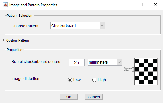
Expand the Custom Pattern panel, to see more options.

Import Custom Pattern Detector Class
The above UI shows a drop-down list for pattern selection. By default, the app does not include a pattern detector for AprilTags. You can create a custom pattern detector class and then add it to the list to use in the app. For more information on how to create a custom pattern, click on the information icon (![]() ). A custom pattern detector class for AprilTags has been provided in MyCustomAprilTagPatternDetector.m file. This class contains UI code for parameters needed by the detector and functions for detecting and processing the custom AprilTags calibration pattern.
). A custom pattern detector class for AprilTags has been provided in MyCustomAprilTagPatternDetector.m file. This class contains UI code for parameters needed by the detector and functions for detecting and processing the custom AprilTags calibration pattern.
The example uses the configureUIComponents() function to configure the UI component and the initializePropertyValues() to initialize it. The helperDrawImageAxesLabels function, included at the end of the example, is used to render the origin, X-axis and Y-axis labels in the calibration images displayed in the Camera Calibrator app dialog.
The main calibrations functions are:
detectPatternPoints() - Detects and localizes the AprilTags from the captured images and sorts them for use as key points in the calibration procedure. This function is implemented using helperDetectAprilTagCorners function, given at the end of the example.
generateWorldPoints() - Computes world coordinates for the corresponding image coordinates in the AprilTag pattern. This function is implemented using helperGenerateAprilTagPattern function, given at the end of the example.
Import the custom pattern detector class by clicking on the Import Pattern Detector button under Custom Pattern panel. Choose the class file MyCustomAprilTagPatternDetector.m. If there are no errors in the class, then you will see the following view:
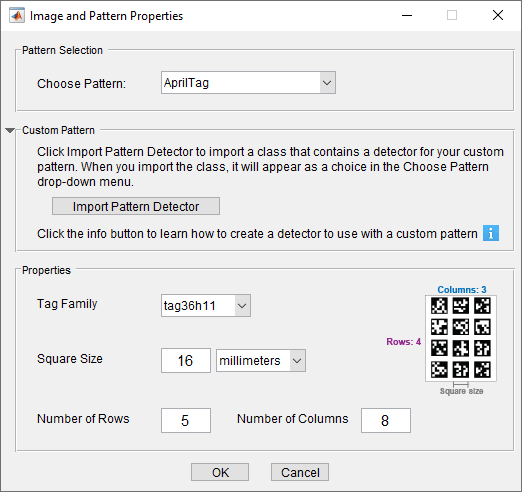
For this example, all the fields in the Properties panel have correct values. But you can customize these values to fit your needs. Note that Square Size represents the width of the tag in world units and is also assumed to be equal to the spacing between each tag in the image.
Click OK and the Data Browser pane displays a list of images with IDs, as shown below:
These images will contain the detected pattern. To view an image, select it from the Data Browser pane.
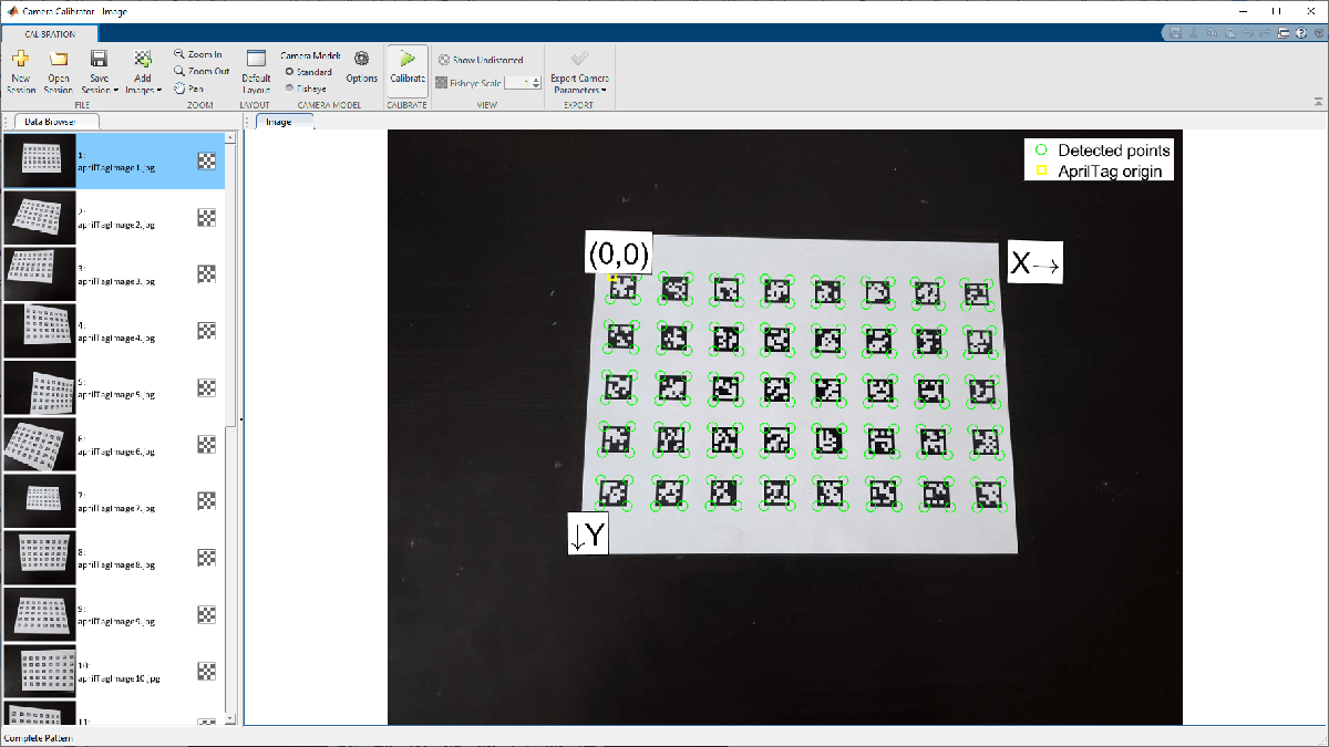
Estimate Camera Parameters
At this point, camera calibration process is the same as given in Using the Single Camera Calibrator App.
With the default calibration settings, click the Calibrate button on the Calibration tab. Visualize the accuracy of the calibration by inspecting the Reprojection Errors pane and then visualize estimates of the extrinsic camera parameters in the Camera-centric pane which shows the patterns positioned with respect to the camera.

Supporting Functions and Classes
helperGenerateAprilTagPattern generates an AprilTag based calibration pattern.
function calibPattern = helperGenerateAprilTagPattern(imdsTags,tagArragement,tagFamily)

numTags = tagArragement(1)*tagArragement(2);
tagIds = zeros(1,numTags);

% Read the first image.
I = readimage(imdsTags,3);
Igray = im2gray(I);

% Scale up the thumbnail tag image.
Ires = imresize(Igray,15,"nearest");

% Detect the tag ID and location (in image coordinates).
[tagIds(1), tagLoc] = readAprilTag(Ires,tagFamily);

% Pad image with white boundaries (ensures the tags replace the black
% portions of the checkerboard).
tagSize = round(max(tagLoc(:,2)) - min(tagLoc(:,2)));
padSize = round(tagSize/2 - (size(Ires,2) - tagSize)/2);
Ires = padarray(Ires,[padSize,padSize],255);

% Initialize tagImages array to hold the scaled tags.
tagImages = zeros(size(Ires,1),size(Ires,2),numTags);
tagImages(:,:,1) = Ires;

for idx = 2:numTags

    I = readimage(imdsTags,idx + 2);
    Igray = im2gray(I);
    Ires = imresize(Igray,15,"nearest");
    Ires = padarray(Ires,[padSize,padSize],255);

    tagIds(idx) = readAprilTag(Ires,tagFamily);

    % Store the tag images.
    tagImages(:,:,idx) = Ires;

end

% Sort the tag images based on their IDs.
[~, sortIdx] = sort(tagIds);
tagImages = tagImages(:,:,sortIdx);

% Reshape the tag images to ensure that they appear in column-major order
% (montage function places image in row-major order).
columnMajIdx = reshape(1:numTags,tagArragement)';
tagImages = tagImages(:,:,columnMajIdx(:));

% Create the pattern using 'montage'.
imgData = montage(tagImages,Size=tagArragement);
calibPattern = imgData.CData;

end
helperDetectAprilTagCorners detects AprilTag calibration pattern in images.
function [imagePoints,boardSize,imagesUsed] = helperDetectAprilTagCorners(imdsCalib,tagArrangement,tagFamily)

% Get the pattern size from tagArrangement.
boardSize = tagArrangement*2 + 1;

% Initialize number of images and tags.
numImages = length(imdsCalib.Files);
numTags = tagArrangement(1)*tagArrangement(2);

% Initialize number of corners in AprilTag pattern.
imagePoints = zeros(numTags*4,2,numImages);
imagesUsed = zeros(1,numImages);

% Get checkerboard corner indices from AprilTag corners.
checkerIdx = helperAprilTagToCheckerLocations(tagArrangement);

for idx = 1:numImages

    % Read and detect AprilTags in image.
    I = readimage(imdsCalib,idx);
    [tagIds,tagLocs] = readAprilTag(I,tagFamily);

    % Accept images if all tags are detected.
    if numel(tagIds) == numTags
        % Sort detected tags using ID values.
        [~,sortIdx] = sort(tagIds);
        tagLocs = tagLocs(:,:,sortIdx);

        % Reshape tag corner locations into a M-by-2 array.
        tagLocs = reshape(permute(tagLocs,[1,3,2]),[],2);

        % Populate imagePoints using checkerboard corner indices.
        imagePoints(:,:,idx) = tagLocs(checkerIdx(:),:);
        imagesUsed(idx) = true;
    else
        imagePoints(:,:,idx) = [];
    end

end

end
helperAprilTagToCheckerLocations converts AprilTag corners to checkerboard corners.
function checkerIdx = helperAprilTagToCheckerLocations(tagArrangement)

numTagRows = tagArrangement(1);
numTagCols = tagArrangement(2);
numTags = numTagRows * numTagCols;

% Row index offsets.
rowIdxOffset = [0:numTagRows - 1; 0:numTagRows - 1];

% Row indices for first and second columns in board.
col1Idx = repmat([4 1]',numTagRows,1);
col2Idx = repmat([3 2]',numTagRows,1);
col1Idx = col1Idx + rowIdxOffset(:)*4;
col2Idx = col2Idx + rowIdxOffset(:)*4;

% Column index offsets
colIdxOffset = 0:4*numTagRows:numTags*4 - 1;

% Implicit expansion to get all indices in order.
checkerIdx = [col1Idx;col2Idx] + colIdxOffset;

end
helperDrawImageAxesLabels renders the origin, X-axis and Y-axis labels in the calibration images displayed in the calibrator app.
function [originLabel,xLabel,yLabel] = helperDrawImageAxesLabels(boardSize,imagePoints)

    numBoardRows = boardSize(1)-1;
    numBoardCols = boardSize(2)-1;

    % Reshape checkerboard corners to boardSize shaped array
    boardCoordsX = reshape(imagePoints(:,1), [numBoardRows,numBoardCols]);
    boardCoordsY = reshape(imagePoints(:,2), [numBoardRows,numBoardCols]);
    boardCoords = cat(3, boardCoordsX,boardCoordsY);

    % Origin label (check if origin location is inside the image)
    if ~isnan(boardCoordsX(1,1))
        p1 = boardCoords(1,1,:);

        refPointIdx = find(~isnan(boardCoordsX(:,1)),2);
        p2 = boardCoords(refPointIdx(2),1,:);

        refPointIdx = find(~isnan(boardCoordsX(1,:)),2);
        p3 = boardCoords(1,refPointIdx(2),:);

        [loc, theta] = getAxesLabelPosition(p1,p2,p3);

        originLabel.Location = loc;
        originLabel.Orientation = theta;
    else
        originLabel = struct;
    end

    % X-axis label
    firstRowIdx = numBoardCols:-1:1;
    refPointIdx13 = find(~isnan(boardCoordsX(1,firstRowIdx)),2);
    refPointIdx13 = firstRowIdx(refPointIdx13);

    p1 = boardCoords(1,refPointIdx13(1),:);
    p3 = boardCoords(1,refPointIdx13(2),:);

    refPointIdx2 = find(~isnan(boardCoordsX(:,refPointIdx13(1))),2);
    p2 = boardCoords(refPointIdx2(2),refPointIdx13(1),:);

    [loc, theta] = getAxesLabelPosition(p1,p2,p3);
    theta = 180 + theta;

    xLabel.Location    = loc;
    xLabel.Orientation = theta;

    % Y-axis label
    firstColIdx = numBoardRows:-1:1;
    refPointIdx12 = find(~isnan(boardCoordsX(firstColIdx,1)),2);
    refPointIdx12 = firstColIdx(refPointIdx12);

    p1 = boardCoords(refPointIdx12(1),1,:);
    p2 = boardCoords(refPointIdx12(2),1,:);

    refPointIdx3 = find(~isnan(boardCoordsX(refPointIdx12(1),:)), 2);
    p3 = boardCoords(refPointIdx12(1),refPointIdx3(2),:);

    [loc,theta] = getAxesLabelPosition(p1,p2,p3);

    yLabel.Location = loc;
    yLabel.Orientation = theta;

    %--------------------------------------------------------------
    % p1+v
    %  \
    %   \     v1
    %    p1 ------ p2
    %    |
    % v2 |
    %    |
    %    p3
    function [loc,theta] = getAxesLabelPosition(p1,p2,p3)
        v1 = p3 - p1;
        theta = -atan2d(v1(2),v1(1));

        v2 = p2 - p1;
        v = -v1 - v2;
        d = hypot(v(1),v(2));
        minDist = 40;
        if d < minDist
            v = (v / d) * minDist;
        end
        loc = p1 + v;
    end
    %--------------------------------------------------------------

end