Estimate Pose of Moving Camera Mounted on a Robot
This example shows how to perform and verify hand-eye calibration for a robot arm or manipulator equipped with a camera in the eye-in-hand configuration (also referred to as moving camera configuration).
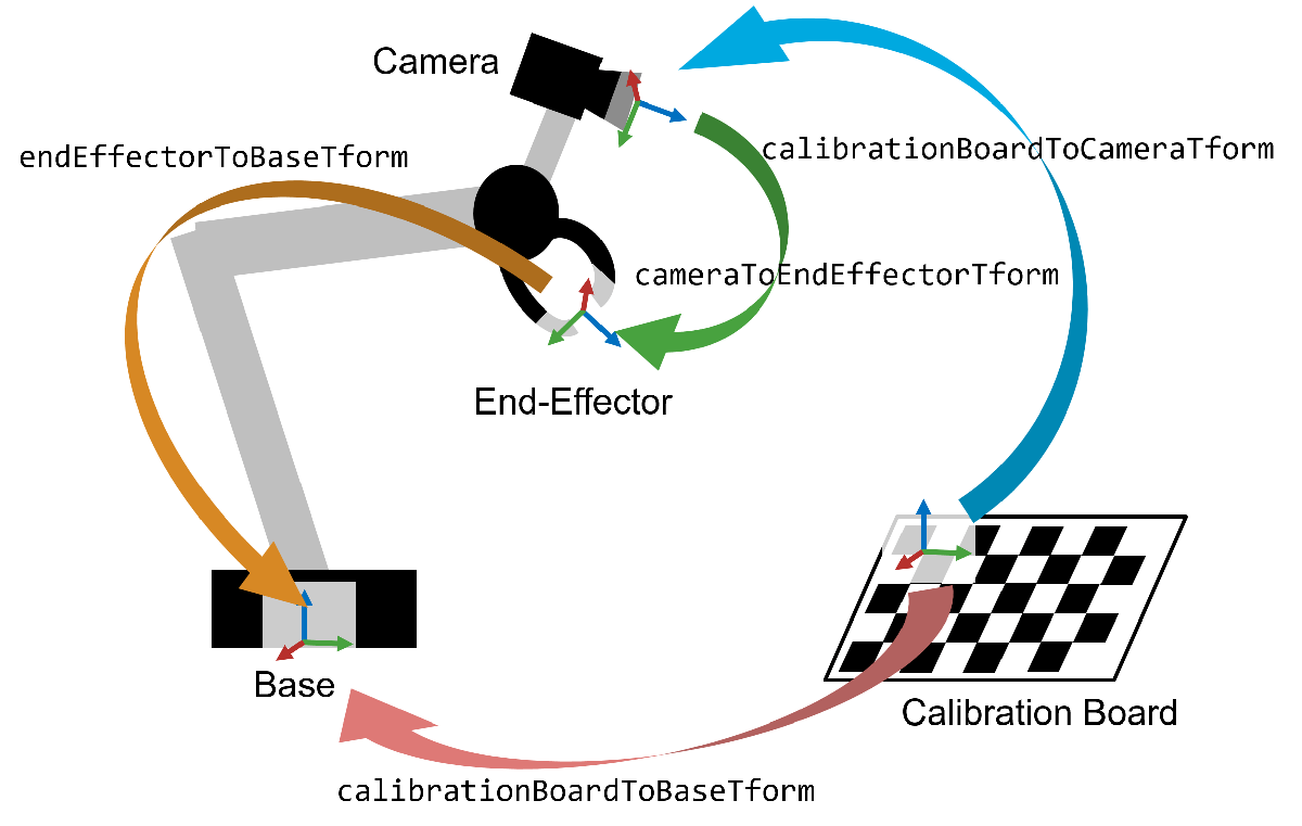
Overview
Performing hand-eye calibration is useful for operating a robot arm equipped with an end-effector, referred to as 'the hand' that relies on visual data from a camera. Once hand-eye calibration is complete, the robot arm can accurately move to specific pixel locations identified by the camera. This capability is fundamental for executing precise pick-and-place tasks, such as sorting, stacking, and bin picking, even in scenarios where the camera's exact position and orientation are unknown.
Robot-camera systems are available in two configurations: moving camera (also referred to as eye-in-hand) and stationary camera (also referred to as eye-to-hand). In the moving camera configuration, the camera is mounted directly on the robot arm's end-effector. Conversely, in the stationary camera configuration, the camera is fixed on a stationary object with the robot arm within its field of view. This example focuses on hand-eye calibration specifically for a moving camera configuration, yet the principles and techniques described can be adapted to suit stationary camera configuration.
In this example, you first calibrate the camera to determine its intrinsic parameters. Following this, robot hand-eye calibration is performed. The outcome of this calibration is then utilized to transform image points to coordinates in the robot's world frame. This example requires the Computer Vision Toolbox and Robotics System Toolbox.
Estimate Camera Intrinsic Parameters
Camera calibration is the first step in hand-eye calibration. This step focuses on estimating the intrinsic parameters (focal length, distortion, etc.) of the camera, which are required for removing image distortion and estimating the camera's pose relative to a calibration board.
To accurately calibrate your camera, collect 10-20 calibration images using the guidelines listed in Prepare Camera and Capture Images for Camera Calibration. In this example, the camera was calibrated with a checkerboard calibration pattern using the Using the Single Camera Calibrator App and the camera parameters were exported to cameraParams.mat.
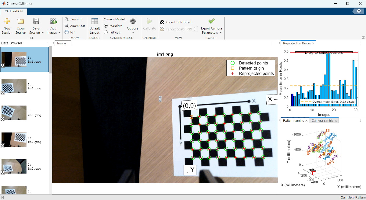
Load these estimated camera intrinsic parameters into MATLAB.
ld = load("cameraParams.mat");
intrinsics = ld.cameraParams.Intrinsics;
Collect Images for Robot Hand-Eye Calibration
For robot hand-eye calibration, you must take 15-30 photos from different perspectives. You should ensure the set of robot poses covers a wide range of the robot manipulator workspace. Using these images and the intrinsic parameters of the camera, you can determine the transformation between the calibration board and the camera.
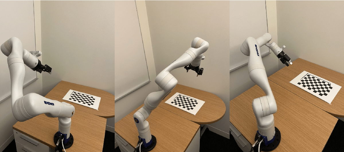
It's important to ensure that the calibration board remains fully visible within the camera's field of view throughout this process. To optimize accuracy, capture a distinct set of images for the camera calibration process separate from those used for robot hand-eye calibration. For each pose, save a camera image along with the robot joint angles. This example uses a KINOVA Gen3 robot arm, which has a camera mounted near the end-effector. The Robotics System Toolbox Support Package for KINOVA Gen3 Manipulators includes tools to collect camera images and their corresponding pose angles in addition to offering capabilities to control the movement of the arm. Load the camera images into an imageDatastore in MATLAB.
numPoses = 30;
imds = imageDatastore("calibrationData");
montage(imds)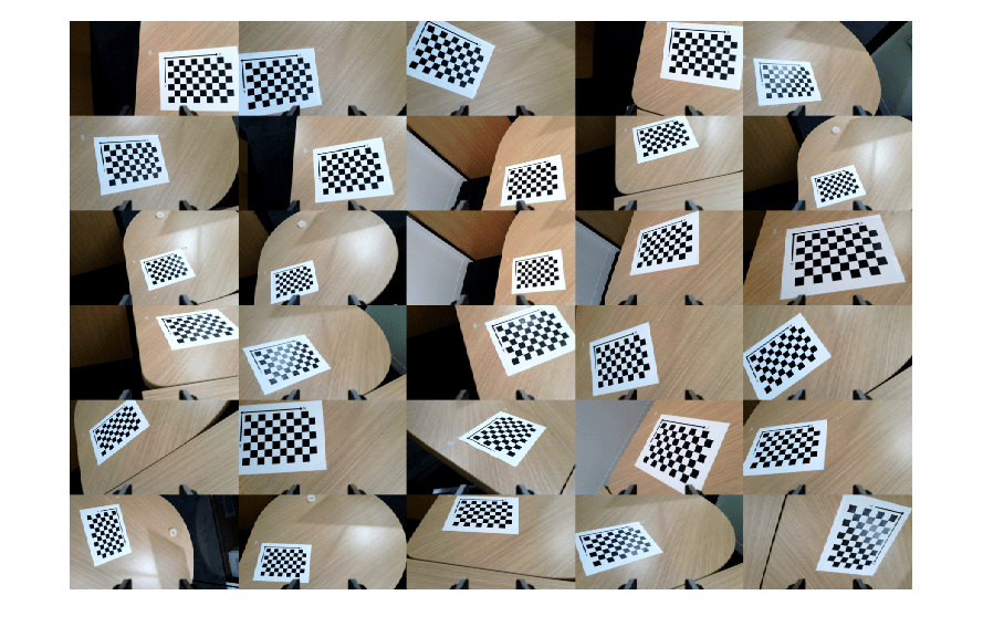
Estimate Camera Extrinsics
In this step, you estimate the camera's extrinsic parameters, which involve determining the transformation from the calibration board's origin to the camera for each pose. The extrinsics estimation process determines the location of the calibration checkerboard points within the undistorted image. These points are then used to determine the camera's position and orientation relative to the calibration board. For details on the camera extrinsics estimation process, see estimateExtrinsics.
squareSize = 0.022; % Measured in meters
camExtrinsics(numPoses,1) = rigidtform3d;

% Estimate transform from the board to the camera for each pose.
for i = 1:numPoses

    % Undistort the image using the estimated camera intrinsics.
    calibrationImage = readimage(imds,i);
    undistortedImage = undistortImage(calibrationImage,intrinsics);

    % Estimate the extrinsics while disabling the partial checkerboard
    % detections to ensure consistent checkerboard origin across poses.
    [imagePoints, patternDims] = detectCheckerboardPoints(undistortedImage,PartialDetections=false);
    worldPoints = patternWorldPoints("checkerboard",patternDims,squareSize);
    camExtrinsics(i) = estimateExtrinsics(imagePoints,worldPoints,intrinsics);
end
Compute Robot End-Effector to Base Transformations
In this step, you use the robot poses collected earlier to compute the transformations from the robot's end-effector joint to its base for each pose. Load the pose data into MATLAB.
jointConfiguration = load("calibrationData/jntconfig.mat");
jointPositionsDeg = jointConfiguration.jointPositions;
Use loadrobot to load a rigidBodyTree model of the Kinova Gen3 robot. A list of supported robots can be found here.
robotModel = loadrobot("kinovaGen3");
robotModel.DataFormat = "column";
Compute the 4-by-4 transformation from the robot's end-effector joint to its base for each calibration pose. The distances in these transformations are measured in meters.
endEffectorToBaseTform(numPoses,1) = rigidtform3d;
for i = 1:numPoses
    jointPositionsRad = deg2rad(jointPositionsDeg(i,:))'; % Convert the pose angles from degrees to radians.
    endEffectorToBaseTform(i) = getTransform(robotModel,jointPositionsRad,"EndEffector_Link");
end
Estimate the Camera to End-Effector Transformation
Use the estimateCameraRobotTransform function to estimate the camera to end-effector transform for the moving camera (or the eye-in-hand) configuration. To use the stationary camera (or the eye-to-hand) configuration, see the Estimate Pose of Fixed Camera Relative to Robot Base (Robotics System Toolbox) example.
config = "moving-camera";
cameraToEndEffectorTform = estimateCameraRobotTransform(camExtrinsics,endEffectorToBaseTform,config)
cameraToEndEffectorTform =
rigidtform3d with properties:
Dimensionality: 3
Translation: [-0.0154 0.0468 0.0041]
R: [3×3 double]
A: [-0.9958 0.0919 -0.0002 -0.0154
-0.0919 -0.9956 0.0185 0.0468
0.0015 0.0184 0.9998 0.0041
0 0 0 1.0000]
The function returns a rigidtform3d object that contains the transformation from the camera to the end-effector joint, which can be used to compute the camera to robot base transformation.
Verify Calibration By Performing Object Pick-up
Verify the calibrated system by instructing the robot to retrieve an object detected within the camera's field of view. This example demonstrates the verification process using an AprilTag attached to a cube. AprilTags are fiducial markers that facilitate accurate camera extrinsic estimation, thus enabling the robot to approach and pick up the cube.
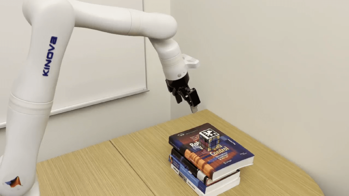
Begin by positioning the robot arm so that the AprilTag is in the camera's field of view. Then, capture an image and record the robot's current pose, including its joint angles.
% Load the test pose angles.
load("testData/poses.mat");
testPose = pose_angles';

% Load and undistort the test image.
testImage = imread("testData/im1.png");
undistortedTestImage = undistortImage(testImage,ld.cameraParams);

% Compute the end-effector joint to base transformation for the test pose.
testPoseRad = deg2rad(testPose);
endEffectorToBaseTformTest = getTransform(robotModel,testPoseRad,"EndEffector_Link");
Use the readAprilTag function to compute the AprilTag to camera transformation.
% Specify the tag family and tag size of the AprilTag.
tagFamily = 'tag36h11';
tagSize = .049; % AprilTag size in meters

% Detect AprilTag in test image.
[~,~,aprilTagToCameraTform] = readAprilTag(undistortedTestImage,tagFamily,intrinsics,tagSize);
Now, multiply the transforms to determine the transformation of the AprilTag in relation to the robot's base.
% Find the transformation from the camera to the robot base.
cameraToBaseTestTform = rigidtform3d(endEffectorToBaseTformTest * cameraToEndEffectorTform.A);

% Find the transformation from the April Tag to the robot base.
tagToBaseTestTform = cameraToBaseTestTform.A * aprilTagToCameraTform.A;
cubePosition = tagToBaseTestTform(1:3,4)
cubePosition = 3×1

    0.6930
   -0.0060
    0.1795
The AprilTag's position is 0.693 meters in front of, 0.006 meters to the left of, and 0.179 meters above the base of the robot.
To verify the accuracy of your calculation, create a plot that the displays the positions of the robot, camera, and cube. The visual representation can then be compared with the initial test setup.
% Show the 3D Robot model, with the base at the origin.
show(robotModel,testPoseRad);
hold on

% Show the estimated positions and orientations of the camera and cube.
plotCamera(AbsolutePose = cameraToBaseTestTform, Opacity=0, size=0.02)
scatter3(cubePosition(1), cubePosition(2), cubePosition(3), 300, 'square', 'filled')
cubeRotationQuaternion = rotm2quat(tagToBaseTestTform(1:3,1:3));
plotTransforms(cubePosition', cubeRotationQuaternion)
title("Robot Arm and Estimated Position of AprilTag Cube")
xlim([-.3,.9])
ylim([-.5, .5])
zlim([-.2,.9])
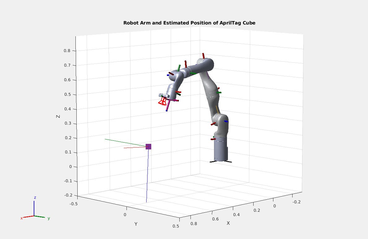
Given that the plot markers for both the camera and the cube are approximately in the right position and orientation, pass the coordinates of the cube to the robot and command it to move the end-effector joint to the correct position. The Robotics System Toolbox and ROS Toolbox provide functions to calculate the motor inputs needed to move the end-effector joint into position and send those controls to the robot. The inverseKinematics function from the Robotics System Toolbox provides a solver to find a set of joint angles to accomplish a end-effector joint position and rotation relative to the robot base.
In the following video, the robot calculates the position of the cube using hand-eye calibration and moves its gripper to the cube's coordinates to pick it up.

Conclusion
In this example, robot hand-eye calibration facilitated an accurate pick-and-place operation, allowing the robot arm to locate an object in the camera's field of view and translate that location to the robot's coordinate system. Hand-eye calibration is useful for integrating a camera into a robot arm system whenever the precise location of the camera is unknown or difficult to measure.
References
[1] Tsai, R.Y. and Lenz, R.K., 1989. A new technique for fully autonomous and efficient 3d robotics hand/eye calibration. IEEE Transactions on robotics and automation, 5(3), pp.345-358.