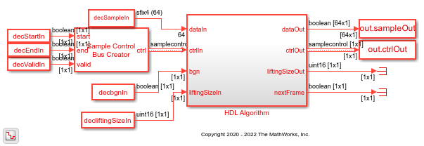
NR LDPC Decoder
Decode LDPC code according to 5G NR standard
Libraries:
Wireless HDL Toolbox /
Error Detection and Correction
Description
The NR LDPC Decoder block implements a low-density parity-check (LDPC) decoder with hardware-friendly control signals. The block accepts punctured log-likelihood ratio (LLR) values, a stream of control signals, a base graph number, and lifting sizes. The block outputs decoded bits, a stream of control signals, lifting sizes, and a signal that indicates when the block is ready to accept new inputs.
This block provides an option to implement layered belief propagation with either the
normalized min-sum approximation algorithm or the min-sum approximation algorithm. This
implementation matches that of the function nrLDPCDecode (5G Toolbox). You can use this block
for channel coding of downlink and uplink shared channels and paging channel according to 5G
new radio (NR) standard TS 38.212 [1].
The NR LDPC Decoder block supports scalar and 64-element column vector inputs. The block supports the early termination feature to help improve decoding performance and faster convergence speeds at high signal noise ratio (SNR) conditions. The block enables decoding of multiple code rates to help achieve high throughput efficiency with a high degree of code rate flexibility. The block provides an architecture suitable for HDL code generation and hardware deployment. For more information, see Algorithms.
Examples
LDPC Encode and Decode of 5G NR Streaming Data
Simulate NR LDPC Encoder and NR LDPC Decoder blocks and compare their hardware-optimized results with results from 5G Toolbox™ functions.
LDPC Decode 5G NR Streaming Data for Multiple Code Rates with Early Termination
Use multiple code rates and early termination criteria features in NR LDPC Decoder block.
Ports
Input
Input log-likelihood ratio (LLR) values, specified as a scalar or a column vector of size 64.
The data type of this input must be a signed fixed-point with a word length from 4 to 16 bits. For more information on how to specify vector input data, see Specifying Vector Input.
Data Types: int8 | int16 | fixed point
Control signals accompanying the sample stream, specified as a
samplecontrol bus. The bus includes the start,
end, and valid control signals, which indicate the
boundaries of the frame and the validity of the samples.
start— Indicates the start of the input frameend— Indicates the end of the input framevalid— Indicates that the data on the input data port is valid
For more details, see Sample Control Bus.
Data Types: bus
Base graph number, specified as a scalar. When this value is 0,
the block applies bgn 1. When this value is 1,
the block applies bgn 2. For more information about bgn
1 and bgn 2, see section 5.3.2, of TS 38.212 [1].
Data Types: Boolean
Input lifting size, specified as a scalar.
For an invalid liftingSize value, the block discards the current frame and waits for the new frame. For more information about the supported lifting size values, see section 5.3.2, of TS 38.212 [1].
Data Types: uint16
Number of iterations, specified as a integer in the range from 1 to 63.
If you specify iter as a value greater than 63, the block
automatically sets the iter value to 8 and
performs the decoding operation.
Dependencies
To enable this port, set the Source for number of
iterations parameter to Input port.
Data Types: uint8
Number of rows, specified as a scalar.
When you set the bgn value to 0 the block
supports the number of rows in the range from 4 to 46. When you set the
bgn value to 1, the block supports the
number of rows in the range from 4 to 42.
Dependencies
To enable this port, select the Enable multiple code rates parameter.
Data Types: fixdt(0,6,0)
Output
Decoded output data bits, returned as a scalar or a column vector of size 64.
The block outputs data bits in a similar format as the input LLR values. Extract these output data bits in a similar format for further processing.
Data Types: Boolean
Control signals accompanying the sample stream, returned as a samplecontrol
bus. The bus includes the start, end, and
valid control signals, which indicate the boundaries of the frame
and the validity of the samples.
start— Indicates the start of the output frameend— Indicates the end of the output framevalid— Indicates that the data on the output data port is valid
For more details, see Sample Control Bus.
Data Types: bus
Output lifting size, returned as a scalar.
Data Types: uint16
Block ready indicator, returned as a Boolean scalar.
The block sets this signal to 1 (true) when
the block is ready to accept the start of the next frame. If the block receives an
input ctrl.start signal while nextFrame is
0 (false), the block discards the frame in
progress and begins processing the new data.
Data Types: Boolean
Actual number of iterations the block takes to decode the output, returned as a scalar.
Dependencies
To enable this port, set the Decoding termination criteria
parameter to Early.
Data Types: uint8
Parity check status indicator, returned as a Boolean scalar. The port indicates the status of the parity check after the decoding operation.
0— Indicates that the parity check failed1— Indicates that the parity check passed
Dependencies
To enable this port, select the Enable parity check output port parameter.
Data Types: Boolean
Parameters
Select the type of algorithm. For more information, see Algorithm (5G Toolbox).
Specify the scaling factor.
Dependencies
To enable this parameter, set the Algorithm parameter to
Normalized min-sum.
Select the decoding termination criteria.
Max— Terminates decoding when the block reaches the number of iterations specified through the Number of iterations parameter or through the iter input portEarly— Terminates decoding when all of the parity checks are met or when the block reaches the maximum number of iterations specified through the Maximum number of iterations parameter or through the iter input port
Select the source for specifying the number of iterations.
You can set the number of iterations by using either an input port or a parameter.
Select
Propertyto enable either the Number of iterations parameter or the Maximum number of iterations parameter.Select
Input portto enable the iter port.
Specify the number of iterations.
Dependencies
To enable this parameter, set the Decoding termination
criteria parameter to Max and the
Source for number of iterations parameter to
Property.
Specify the maximum number of iterations.
Dependencies
To enable this parameter, set the Decoding termination
criteria parameter to Early and the
Source for number of iterations parameter to
Property.
Select this parameter to enable the numRows input port to support multiple code rates. For more information about multiple code rates, see Multiple Code Rates.
Select this parameter to enable the parityCheck output port to view the status of the parity check.
More About
Vector input data for the block must be specified as a column vector of size 64. You
must provide inputs as an integer number of ceil(liftingSize/64) clock cycles.
The total number of clock cycles that the block requires to receive a frame of LLR
values for decoding is equal to n x
ceil(liftingSize/64), where n is the number of columns in the parity check
matrix. n depends on the base graph number, specified by the
bgn input port. When the bgn port value is
0, the block sets n to 66. When the
bgn port value is 1, the block sets
n to 50.
These sections show how the block accepts input LLR values based on the liftingSize and bgn port values.
For a liftingSize input value of 2 and
bgn input value of 0, the block can accept 132
LLRs. In this case, the block accepts the first two LLR input bits in each clock cycle and
ignores the remaining 62 elements in that clock cycle. The total number of clock cycles
the block requires to receive a frame of LLR values is 66.
The Ln elements represent LLR bits, and the X elements represent ignored values.
| Input LLR Values | Number of Clock Cycles | |||||
|---|---|---|---|---|---|---|
| 1 Clock Cycle | 2 Clock Cycles | 3 Clock Cycles | 4 Clock Cycles | ... | 66 Clock Cycles | |
data[0] | L0 | L2 | L4 | L6 | ... | L130 |
data[1] | L1 | L3 | L5 | L7 | ... | L131 |
| ... | X | X | X | X | X | X |
data[63] | X | X | X | X | X | X |
For a liftingSize input value of 104 and
bgn input value of 0, the block can accept 6,864
LLRs. In this case, the block accepts 104 LLR values in two clock cycles: 64 LLRs in the
first clock cycle and 40 LLRs in the second clock cycle. The block ignores the remaining
24 elements in the second clock cycle. The total number of clock cycles the block requires
to receive input LLR values is 132.
The Ln elements represent LLR bits, and the X elements represent ignored values.
| Input LLR Values | Number of Clock Cycles | |||||||
|---|---|---|---|---|---|---|---|---|
| 1 Clock Cycle | 2 Clock Cycles | 3 Clock Cycles | 4 Clock Cycles | ... | ... | 131 Clock Cycles | 132 Clock Cycles | |
data[0] | L0 | L64 | L104 | L168 | ... | ... | L6760 | L6824 |
data[1] | L1 | L65 | L105 | L169 | ... | ... | L6761 | L6825 |
| ... | ... | ... | ... | ... | ... | ... | ||
| ... | ... | L103 | ... | L207 | ... | ... | ... | L6863 |
| ... | ... | X | ... | X | ... | ... | ... | X |
data[63] | L63 | X | L167 | X | ... | ... | L6823 | X |
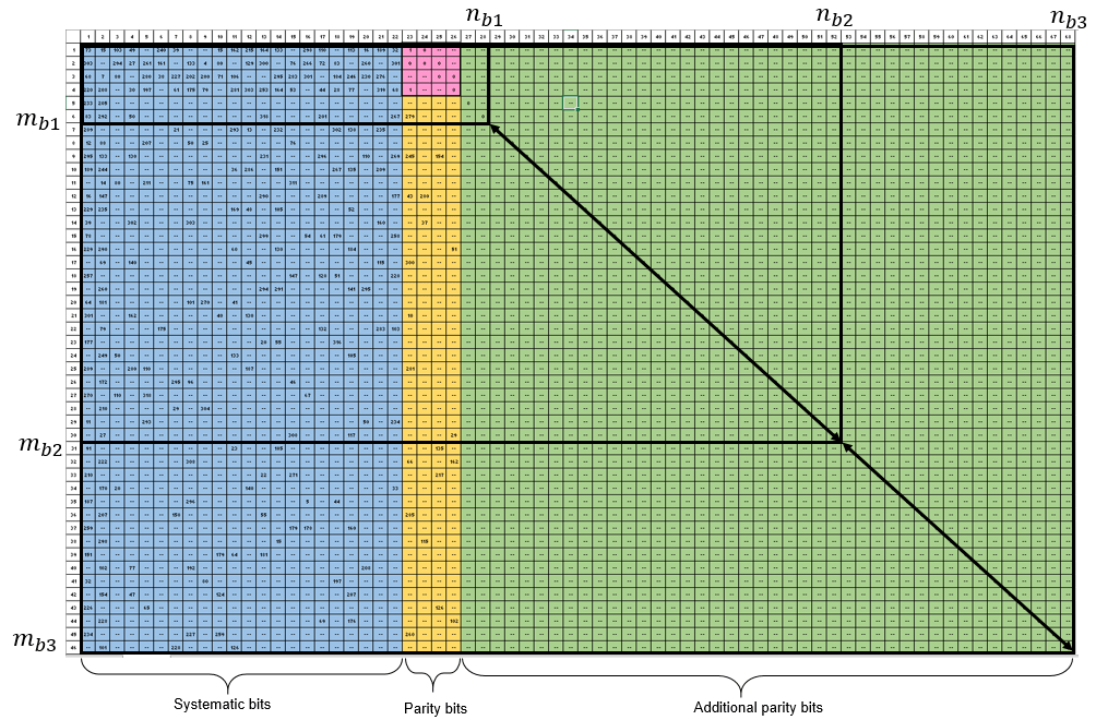
NR LDPC codes can support flexible code rates based on the parity check matrix (PCM) extension to achieve high throughputs and meet low latency requirements. The block supports multiple code rates by varying the number of rows of the parity check matrix.
For LDPC codes, the base parity check matrix
(Hb) is a product of the number of rows
(mb) and the number of columns
(nb) of the matrix. The output
(K) of the block is calculated as
kb x Z, where
Z is the expansion factor or lifting size that can be in the range from
2 to 384, and kb is equal to 22
for bgn value 0 and 10 for
bgn value 1 as defined in the standard [1].
The input size (N) is calculated as, nb x Z, where nb is equal to mb + kb.
This figure shows a parity check matrix marked with a specified number of rows and columns, which you can use to calculate the code rates of the block. The code rate R is calculated as, kb / (kb – 2 + mb) for the specified bgn value. In this figure, the values nb1, nb2, and nb3 indicate the number of columns for the specified bgn value and values mb1, mb2, and mb3 indicate the number of rows for the specified bgn value.
Algorithms
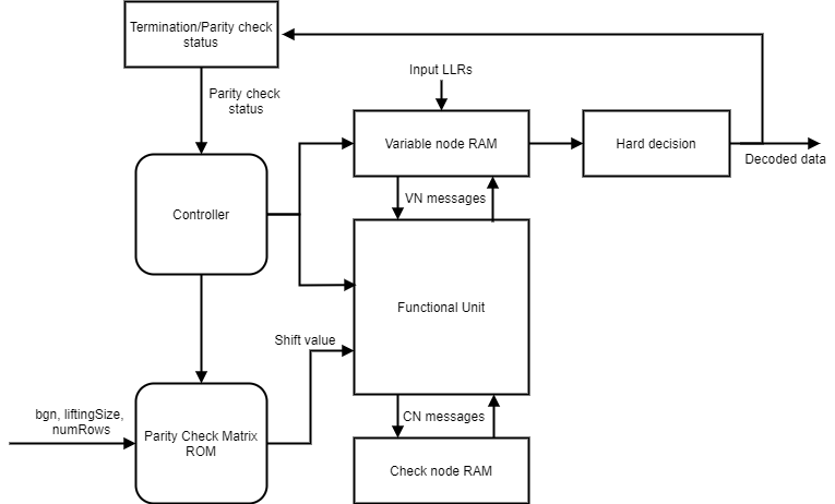
This figure shows the architecture block diagram of the NR LDPC Decoder block. The Controller block controls the layer and iteration count of the decoding process. The Variable node RAM block stores the variable node (VN) messages, and Check node RAM block stores the check node messages (CN). The Functional Unit block calculates the variable node (VN) messages and check node (CN) messages based on the layered belief propagation and either the normalized min-sum approximation algorithm or the min-sum approximation algorithm. The Termination/Parity check status block calculates the parity checks and provides the parity check status after each iteration. For more information about decoding algorithms, see Algorithm (5G Toolbox).
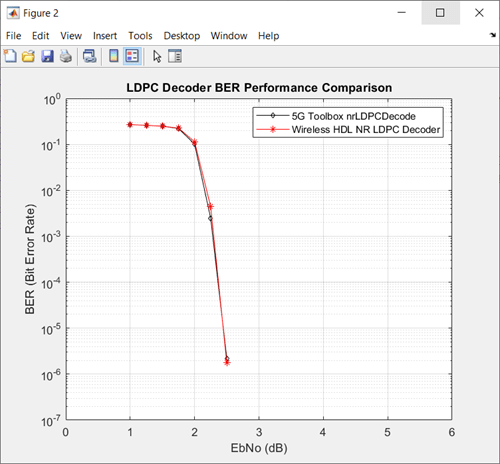
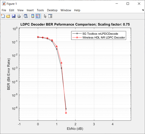
The implementation of the block matches the performance of the function nrLDPCDecode (5G Toolbox).
This plot shows the performance of the block for a 4 bit BPSK-modulated LLR input, when
you set the Algorithm parameter to Min-sum,
the bgn parameter to 0, and the
liftingSize parameter to 384.
This plot shows the performance of the block for a 4 bit BPSK-modulated LLR input, when
you set the Algorithm parameter to Normalized
min-sum, the bgn parameter to
0, and the liftingSize parameter to
384.
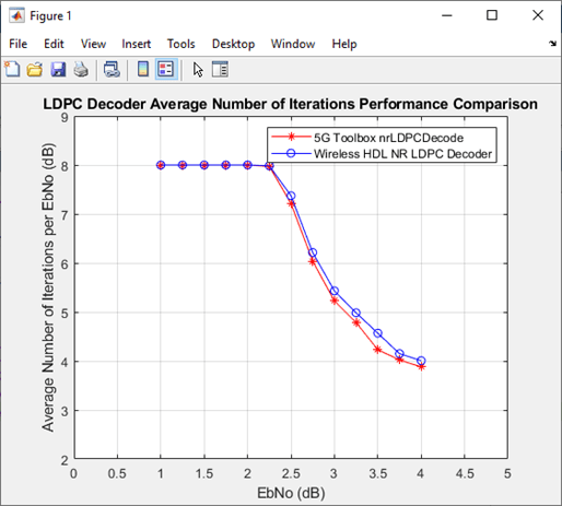
This plot shows the average number of iterations taken to decode the data per EbNo for a
4-bit BPSK-modulated LLR input, when you set the Algorithm parameter to
Min-sum and the Decoding termination
criteria parameter to Early.
The latency of the block varies based on the values of the bgn, liftingSize, and numRows input ports and the number of iterations. Because the latency varies, use the nextFrame control signal output port to determine when the block is ready for a new input frame.
The latency of the block is equal to r x (t +
(m x 8) x
ceil(liftingSize/64) + t
+ m x (7 –
ceil(liftingSize/64))) + (n
x liftingSize) + 18. In this calculation, r is the number of iterations,
n is the number of columns in the parity check matrix,
t is twice the total number of non –1 elements in the parity check
matrix, m is the number of rows in the parity check matrix, and
d is the pipeline delays. When you select the Enable
multiple code rates parameter, d is 26. Otherwise,
d is 18.
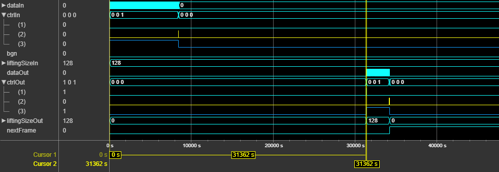
This figure shows a Logic Analyzer waveform of the sample output of the NR LDPC
Decoder block with latency. In this case, the bgn and
liftingSize input port values are set to 0 and
128, respectively, and the Number of iterations
parameter is set to 8. The latency of the block is 31,362 clock
cycles.
For vector inputs, the latency of the block is equal to r x (t +
(m x 9)) + n x
(ceil(liftingSize/64)) +
d. In this calculation, r is the number of iterations,
n is the number of columns in the parity check matrix,
t is twice the total number of non -1 elements in the parity check
matrix, m is the number of rows in the parity check matrix, and
d is the pipeline delays. When you select the Enable
multiple code rates parameter, d is 26. Otherwise,
d is 18.
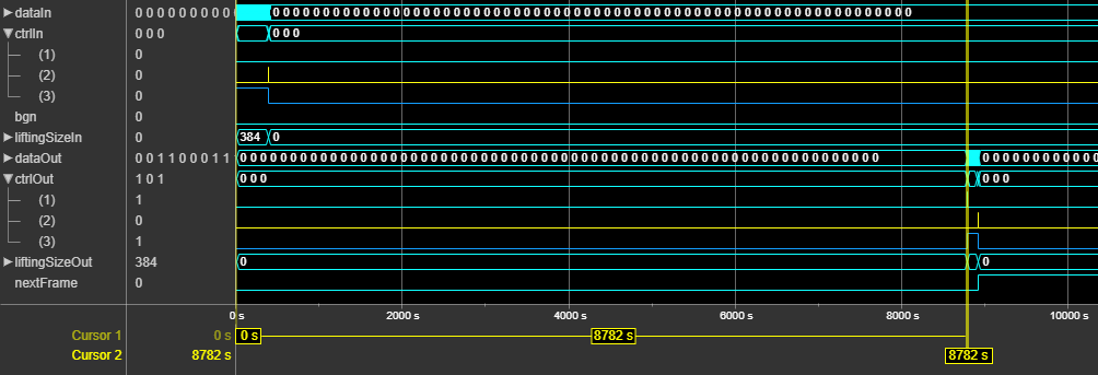
This figure shows a Logic Analyzer waveform of the sample output of the NR LDPC
Decoder block with latency. In this case, the bgn and
liftingSize input port values are set to 0 and
384, respectively, and the Number of iterations
parameter is set to 8. The latency of the block is 8,782 clock
cycles.
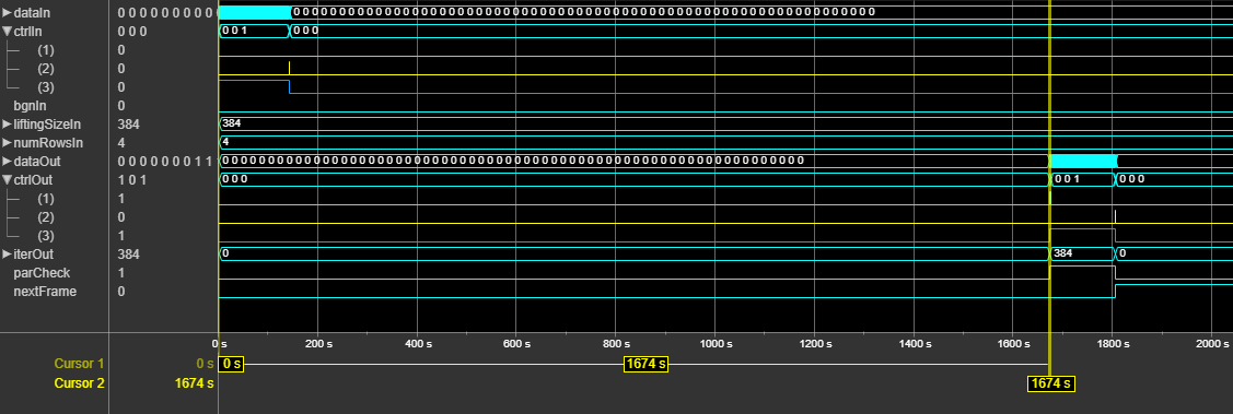
This figure shows a Logic Analyzer waveform of the sample output of the NR LDPC
Decoder block with latency. In this case, the bgn,
liftingSize, and numRows input port values are
set to 0, 384, and 4,
respectively, and the Number of iterations parameter is set to
8. The latency of the block is 1,674 clock cycles.
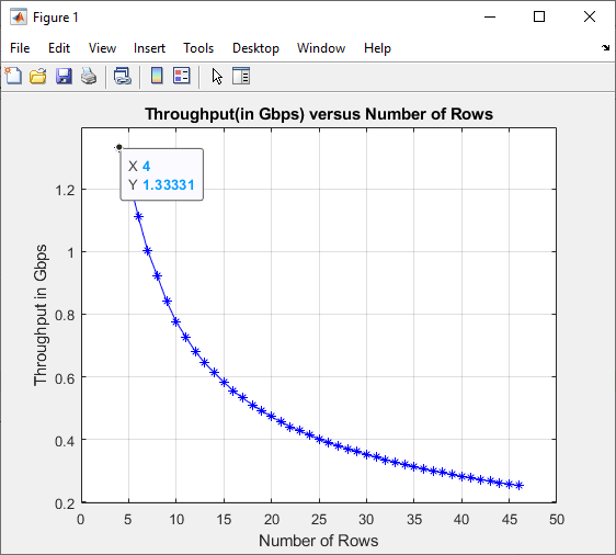
The throughput of the block is calculated as (cwLen / latency) x fmax. In this calculation:
cwLen is the code word length which is equal to kb x Z, where kb is
22for the bgn value0and10for the bgn value1.latency is the latency of the block for the specified configuration
fmax is the maximum operating frequency
For more information about the latency calculation, see Latency. For more information about the maximum operating frequency, see Performance.
This plot shows the throughput versus the number of rows specified at the block input,
when you set the Algorithm parameter to
Min-sum, the Number of iterations
parameter to 8, and the bgn input port to
0.
The performance of the synthesized HDL code varies with your target and synthesis options. It also varies based on the type of algorithm and the word length of the input LLR values.
This table shows the resource and performance data synthesis results of the block, when
you set the Algorithm parameter to Min-sum,
set the Number of iterations parameter to 8, and
specify the input LLR values of data type fixdt(1,4,0). The generated HDL
is targeted to the AMD®
Zynq®
UltraScale+™ RFSoC evaluation board.
| Input Data | Slice LUTs | Slice Registers | Block RAMs | Maximum Frequency in MHz |
|---|---|---|---|---|
| Scalar | 45319 | 54356 | 193 | 299.3 |
| Vector | 68987 | 63458 | 128.5 | 295.2 |
This table shows the resource and performance data synthesis results of the block for
the vector input when you set the Algorithm parameter to
Min-sum, set the Decoding termination
criteria parameter to Max, set the Number
of iterations parameter to 8, select the Enable
multiple code rates parameter, and specify the input LLR values of data type
fixdt(1,4,0). The generated HDL is targeted to the AMD
Zynq
UltraScale+ RFSoC evaluation board.
| Slice LUTs | Slice Registers | Block RAMs | Maximum Frequency in MHz |
|---|---|---|---|
| 74700 | 64425 | 128.5 | 280.3 |
References
[1] 3GPP TS 38.212. “NR; Multiplexing and Channel Coding.” 3rd Generation Partnership Project; Technical Specification Group Radio Access Network.
[2] Gallager, R. “Low-Density Parity-Check Codes.” IEEE Transactions on Information Theory 8, no. 1 (January 1962): 21–28. www.doi.org/10.1109/TIT.1962.1057683.
Extended Capabilities
This block supports C/C++ code generation for Simulink® accelerator and rapid accelerator modes and for DPI component generation.
HDL Coder™ provides additional configuration options that affect HDL implementation and synthesized logic.
This block has one default HDL architecture.
| ConstrainedOutputPipeline | Number of registers to place at
the outputs by moving existing delays within your design. Distributed
pipelining does not redistribute these registers. The default is
|
| InputPipeline | Number of input pipeline stages
to insert in the generated code. Distributed pipelining and constrained
output pipelining can move these registers. The default is
|
| OutputPipeline | Number of output pipeline stages
to insert in the generated code. Distributed pipelining and constrained
output pipelining can move these registers. The default is
|
You cannot generate HDL for this block inside a Resettable Synchronous Subsystem (HDL Coder).
Version History
Introduced in R2020a
MATLAB Command
You clicked a link that corresponds to this MATLAB command:
Run the command by entering it in the MATLAB Command Window. Web browsers do not support MATLAB commands.
选择网站
选择网站以获取翻译的可用内容,以及查看当地活动和优惠。根据您的位置,我们建议您选择:。
您也可以从以下列表中选择网站:
如何获得最佳网站性能
选择中国网站(中文或英文)以获得最佳网站性能。其他 MathWorks 国家/地区网站并未针对您所在位置的访问进行优化。
美洲
- América Latina (Español)
- Canada (English)
- United States (English)
欧洲
- Belgium (English)
- Denmark (English)
- Deutschland (Deutsch)
- España (Español)
- Finland (English)
- France (Français)
- Ireland (English)
- Italia (Italiano)
- Luxembourg (English)
- Netherlands (English)
- Norway (English)
- Österreich (Deutsch)
- Portugal (English)
- Sweden (English)
- Switzerland
- United Kingdom (English)
