HDL OFDM Transmitter
This example shows how to implement an OFDM-based wireless transmitter in Simulink® that is optimized for HDL code generation and hardware implementation.
This example shows the custom design of an orthogonal frequency-division multiplexing (OFDM) based transmitter. The transmitter model in this example accepts payload data and a valid signal to control the transmission. The model enables you to choose the modulation type and the punctured convolutional code rate values. These two parameters control the effective data rate of transmission and are provided through the input ports of transmitter. This transmitter supports the maximum data rate of 3 Mbps.
The transmitter in this example works in conjunction with the receiver in the HDL OFDM Receiver example. The transmitter has a MATLAB® floating point equivalent function described in the HDL OFDM MATLAB References example.
Transmitter Specification
This section explains the specifications of the transmitter related to the OFDM frame configuration and structure, bandwidth, and sample rate.
The transmitter model accepts two parameters, modulation type and code rate, which are explained in the following tables.
Modulation Type
    Value    Represents Modulation Type
    _____    __________________________

      0                BPSK
      1                QPSK
      2                16QAM
      3                64QAM
Code Rate
    Value    Represents Code Rate
    _____    ____________________

      0              1/2
      1              2/3
      2              3/4
      3              5/6
OFDM Frame Structure
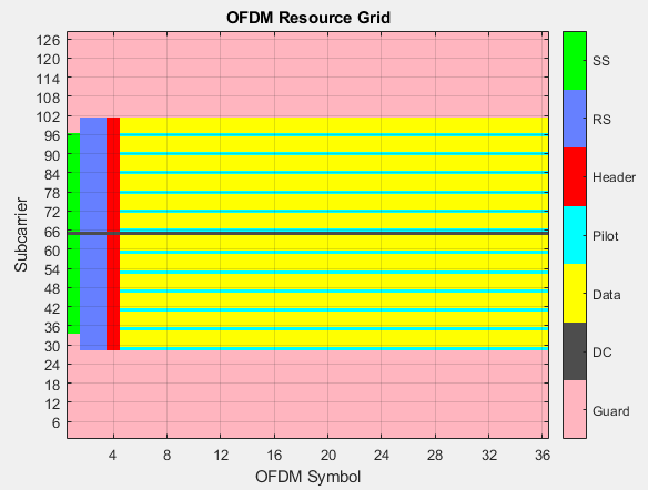
The figure shows the OFDM frame structure in frequency domain. Each OFDM symbol comprises 72 subcarriers, and each OFDM frame consists of 36 OFDM symbols. The frame duration is 3 ms. The first OFDM symbol forms the synchronization sequence (SS), second and third symbols form the reference signals (RS), and the fourth symbol forms the Header. From fifth symbol to the last (36th) symbol forms the data. Pilots are inserted between data such that there is one pilot for every five data subcarriers as shown in this figure. These pilots help to detect and correct phase errors at the receiver.
The OFDM parameters used in the model are given below:
           Parameter              Value
    ________________________    _________

    Sample rate                 1.92 Msps
    Subcarrier spacing          15 kHz
    FFT length                  128
    Bandwidth of OFDM signal    1.4 MHz
    Active subcarriers          72
    Left guard subcarriers      28
    Right guard subcarriers     27
    Cyclic prefix length        32
    Data symbols per frame      32
    Pilots per data symbol      12
Model Architecture
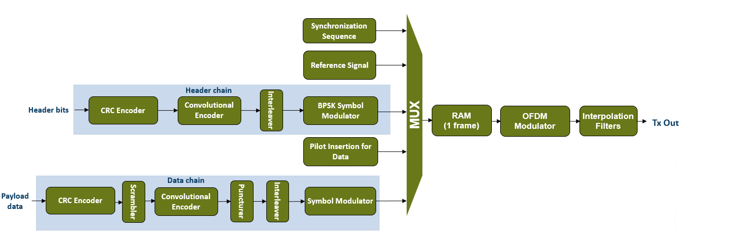
The following figure shows the high-level architecture of the OFDM transmitter. There are five different signals that form the OFDM frame: SS, RS, Header, Pilots, and Data. SS, RS, and Pilots are same for every frame. They are stored in separate lookup tables (LUT) and accessed whenever required. Header and Data vary based on the inputs given to the transmitter. Header bits are formed based on the input modulation type and code rate values. These header bits are processed through the Header chain as shown in the figure. Payload data is provided as an input to the transmitter. This data is processed through multiple stages in the Data chain. Individual stages in the Header and Data chains are explained in further sections.
These five signals are multiplexed based on their valid signals and stored in a RAM. The RAM holds these signals for a duration of one frame. Data stored in the RAM is read out and modulated by the OFDM Modulator block. The OFDM modulated signal streams through an interpolation filter chain to get an interpolated output by a factor of 16.
File Structure
This example contains the following files.
whdlOFDMTransmitter— Top-level model that contains anOFDM Transmittersubsystem. This subsystem refers to thewhdlOFDMTxmodel. An external interface circuit provides inputs and collects outputs from the subsystem.
whdlOFDMTx— Reference model that implements the transmitter.
whdlexamples.OFDMTxParameters— Function that generates parameters required for thewhdlOFDMTxreference model. This function is called in the top-level subsystem mask of the reference model.
whdlexamples.OFDMTxSimulink— Function that initializes and runs thewhdlOFDMTransmittermodel.
whdlexamples.OFDMTx— Function that implements the MATLAB floating point equivalent of thewhdlOFDMTxreference model.
Transmitter Interface
The whdlOFDMTransmitter model shows the OFDM Transmitter subsystem and its interface.
![]()
Model Inputs:
modTypeIndex — Symbol modulation type, specified as a ufix2 scalar. This port accepts values
0,1,2, and3, which correspond to the modulation types BPSK, QPSK, 16-QAM, and 64-QAM, respectively.
codeRateIndex — Code rate of punctured convolutional code, specified as a ufix2 scalar. This port accepts values
0,1,2, and3, which correspond to code rates 1/2, 2/3, 3/4, and 5/6, respectively.
data — Input payload data, specified as a Boolean scalar.
valid — Valid signal for the input data, specified as a Boolean scalar.
Model Outputs:
txData — Transmitter output, returned as a complex scalar with fixdt(1,16,13) datatype sampled at 30.72 Msps.
txValid — Control signal that validates txData, returned as a Boolean scalar sampled at 30.72 Msps.
ready — Control signal that indicates when to sample input data, modTypeIndex, and codeRateIndex values, returned as a Boolean scalar.
Transmitter Structure
The OFDM Transmitter subsystem references the whdlOFDMTx model. It generates an OFDM transmitter waveform by processing input signals at multiple stages.
whdlOFDMTx
![]()
Frame Controller and Input Sampler
The Frame Controller and Input Sampler subsystem generates control signals for later stages of the model. This subsystem also generates a ready output signal that is used for external interfacing. This subsystem samples the input modTypeIndex and codeRateIndex values along with the first valid input sample. In this subsystem, the transport block size for the current frame is selected from the Transport Block Size LUT based on the sampled modTypeIndex and codeRateIndex values. The subsystem also generates control signals for header generation followed by the preamble generation along with the first valid sample. Preamble generation refers to the generation of SS, RS, and Pilot signals. This subsystem asserts the data control signal, the ofdmModReady signal, which indicates the OFDM Modulator block to start modulation.
![]()
Frame Generator
The Frame Generator subsystem generates SS, RS, Header, Pilot, and Data signals, which are later OFDM-modulated. The Generate Preamble Control Signals subsystem in the Frame Generator subsystem, splits the input preambleSet control signal into ss set, rs set, and pilot set control signals, which generate SS, RS, and Pilot signals, respectively.
Frame Generator/Synchronization Sequence
The Synchronization Sequence subsystem accepts ss set control signal generated from the Frame Controller and Input Sampler subsystem. The counter keeps incrementing and returns SS from an LUT. Once ss set becomes inactive, the counter stops. Reference Signals and Pilot subsystems operate in a similar way by storing the sequences in LUTs and accessing them whenever required.
![]()
Frame Generator/Header
The Header subsystem accepts modTypeIndex, codeRateIndex and fftLenIndex as inputs. A headerSet signal starts the header formation. The Header Formation MATLAB function converts the modTypeIndex and codeRateIndex values into their binary equivalents. To learn more about these indices, refer to the Transmitter Specification section in this example. fftLenIndex is not configurable and its value is fixed to 0. fftLenIndex, modTypeIndex, and codeRateIndex are represented using 3, 2, and 2 bits, forming a total of 7 bits. Additionally, 7 spare bits are added, all currently set to 0, forming a total of 14 header bits.
These 14 bits are processed as shown in the figure. For proper error detection, General CRC Generator HDL Optimized block pads 16 CRC bits with [16 12 5 0] as the CRC polynomial. The Convolutional Encoder block encodes these 30 bits, that is 14 + 16, with [171 133] as the polynomial and a constraint length as 7. The encoding is processed in terminated mode, adding 6 null bits to the CRC padded data. After encoding, these 36 bits result in 72 bits due to the 1/2 rate encoding. The output of the Convolutional Encoder block is a two-element vector that is serialized in the Serializer subsystem. The serialized data is interleaved using the Interleaver subsystem. For more information on the Interleaver subsystem, see the HDL Interleaver and Deinterleaver example. The interleaved bits are BPSK-modulated using the LTE Symbol Modulator block to form a header OFDM symbol.
![]()
Frame Generator/Data
The Data subsystem stores input payload data, and processes it through the Data Chain subsystem.
![]()
Frame Generator/Data/Data and Control Signal Generation
The Data and Control Signal Generation subsystem consists of a RAM, where the input payload data is stored. The dataSet signal reads data from this RAM. This subsystem generates start, end, and valid control signals for the RAM data. It also selects the puncture vector based on the codeRateIndex.
![]()
Frame Generator/Data/Data Chain
The General CRC Generator HDL Optimized block appends a 32-bit CRC to the payload data from the RAM with [32 26 23 22 16 12 11 10 8 7 5 4 2 1 0] as the CRC polynomial. This CRC-padded data is scrambled with  as the polynomial and
 [1 0 1 1 1 0 1] as the initial state. The Convolutional Encoder block encodes the scrambled data in terminated mode with [171 133] as the polynomial and constraint length as 7. The encoded output is punctured using the Puncturer block with the puncture vector selected in the Data and Control Signal Generation subsystem. The output of the Puncturer block is a two-element vector. The Serializer subsystem serializes the vector and the Symbol Interleaver subsystem interleaves the resultant serialized data. The supported interleaver depths are 60, 120, 240, and 360 for BPSK, QPSK, 16-QAM, and 64-QAM modulations, respectively. For more information on the Interleaver subsystem, see the HDL Interleaver and Deinterleaver example. The LTE Symbol Modulator block modulates the interleaved data using the modulation pattern selected based on the input modTypeIndex.
![]()
Multiplexer
The Multiplexer subsystem multiplexes the SS, RS, and Pilot signals in the Multiplex Preamble Signals subsystem and the header and data signals in the Multiplex Header and Data Signals subsystem based on the valid signals generated by the Frame Generator subsystem.
![]()
Frame Formation and OFDM Modulation
The Frame Formation and OFDM Modulation subsystem accepts the preambleData and data signals, and then multiplexes and writes them into a RAM, such that it forms an OFDM frame structure as shown in the Transmitter Specification section in this example.
![]()
The Generate OFDM Modulator Valid subsystem generates a valid input signal for the OFDM Modulator block and generates a RAM address to read data from the RAM. The valid signal is in synchronization with the ready signal of the OFDM Modulator. The OFDM Modulator block output is stored inside the FIFO Rate Convertor subsystem RAM. The FIFO Rate Convertor subsystem outputs the stored data at 1.92 Msps only when it has one frame of data in the RAM. Otherwise, it outputs the dummy symbols.
Interpolation Filter Chain
The Interpolation Filter Chain subsystem interpolates the input by a factor of 16 resulting in the waveform with a rate of 30.72 Msps. The CIC Interpolator, FIR Interpolator, and the Discrete FIR Filter blocks are used for interpolation process.
Run Transmitter
Use the runOFDMTransmitterModel script to run the example. This script describes a procedure to initialize, generate inputs, run, and verify the whdlOFDMTransmitter model. You can choose a custom transmitter waveform of your choice in the script.
Alternatively, to run the model, connect the transmitter back-to-back with the receiver in the HDL OFDM Receiver example and run the Simulink model. For more information on how to connect the transmitter and the receiver Simulink models back-to-back, see the HDL OFDM MATLAB References example.
Compare and Verify Results
To compare the output of the Simulink model with the whdlexamples.OFDMTx MATLAB function, run the runOFDMTransmitterModel script. For more information on this MATLAB function, see the HDL OFDM MATLAB References example.
>> runOFDMTransmitterModel
### Searching for referenced models in model 'whdlOFDMTransmitter'.
### Found 1 model reference targets to update.
### Starting serial model reference simulation build.
### Successfully updated the model reference simulation target for: whdlOFDMTx

Build Summary

Model reference simulation targets:

Model       Build Reason                                   Status                        Build Duration
=======================================================================================================
whdlOFDMTx  Target (whdlOFDMTx_msf.mexw64) did not exist.  Code generated and compiled.  0h 6m 10.685s

1 of 1 models built (0 models already up to date)
Build duration: 0h 6m 31.904s
Compare Transmitter output
SQNR in dB: real 43.9688 imag 44.1513
![]()
![]()
![]()
Generate HDL Code
To generate HDL code for this example, you must have an HDL Coder™ license. Run the whdlexamples.OFDMTxSimulink function and use makehdl and makehdltb commands to generate HDL code and HDL testbench for the OFDM Transmitter subsystem. The testbench generation time depends on the simulation time.
You can synthesize the generated HDL code and target on the Xilinx® Zynq®-7000 ZC706 evaluation board. The table shows the post place and route resource usage results. The maximum frequency of operation is 273 MHz.
       Resources       Usage
    _______________    _____

    Slice LUT          5948
    Slice Registers    9397
    RAMB36             13
    RAMB18             17
    DSP48              38
See Also
Blocks
- OFDM Modulator | Puncturer | LTE Symbol Modulator | General CRC Generator HDL Optimized | Convolutional Encoder | Discrete FIR Filter | Serializer1D (HDL Coder)