Modeling Mutual Coupling in Large Arrays Using Embedded Element Pattern
This example demonstrates the embedded element pattern approach to model large finite arrays. Such an approach is only good for very large arrays so that the edge effects may be ignored. It is common to consider an infinite array analysis as a first step for such kind of analysis. This approach is presented in Modeling Mutual Coupling in Large Arrays Using Infinite Array Analysis. The embedded element pattern refers to the pattern of a single element embedded in the finite array, that is calculated by driving the central element in the array and terminating all other elements into a reference impedance [1]-[3]. The pattern of the driven element, referred to as the embedded element, incorporates the effect of coupling with the neighboring elements. It is common to choose the central region/element of the array for the embedded element, depending on whether the array has an even or odd number of elements (for large arrays it does not matter). The pattern of the isolated element (the radiator located in space by itself) changes when it is placed in an array due to the presence of mutual coupling. This invalidates the use of pattern multiplication, which assumes that all elements have the same pattern. To use pattern multiplication to calculate the total array radiation pattern, and improve the fidelity of the analysis, we replace the isolated element pattern with the embedded element pattern.
Analysis Approach
As mentioned in the introduction, it is the aim of this example to illustrate the use of the embedded element pattern when modeling large finite arrays. To do so, you model 2 arrays: first using the pattern of the isolated element, second with the embedded element pattern and compare the results of the two with the full-wave Method of Moments (MoM) based solution of the array. The array performance for scanning at broadside, and for scanning off broadside is established. Finally, you adjust the array spacing to investigate the occurrence of scan blindness and compare against reference results [3]. This example uses center of the X-band as the design frequency.
freq = 10e9;
vp = physconst("lightspeed");
lambda = vp/freq;
Model an Array of Dipoles Using Isolated Element Pattern
In [4], it was discussed that the central element of a 5-by-5 array starts to behave like it is in an infinite array. Such an aperture would correspond to a 10-by-10 array of half-wavelength spaced radiators. You choose to slightly exceed this limit and consider a 11-by-11 array of dipoles.
Nrow = 11;
Ncol = 11;
drow = 0.5*lambda;
dcol = 0.5*lambda;
Dipole as Antenna Element
Choose a dipole as the individual element. Choose its length to be slightly lower than and radius approximately .
mydipole = dipole;
mydipole.Length = 0.47*lambda;
mydipole.Width = cylinder2strip(0.191e-3);
URA with an Isolated Dipole
Create a 11-by-11 URA and assign the isolated dipole as its element. Adjust the spacing to be half-wavelength at 10 GHz. The dipole tilt is now set to zero, so that its orientation matches the array geometry in the Y-Z plane.
myURA2 = phased.URA;
myURA2.Element = mydipole;
myURA2.Size = [Nrow Ncol];
myURA2.ElementSpacing = [drow dcol];
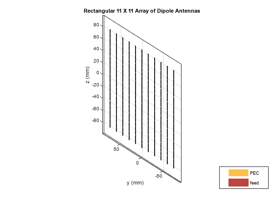
Create Full-Wave Model of the 11-by-11 Array
Use the Antenna Toolbox™ to create a full-wave model of the 11-by-11 array of resonant dipoles. Since the default orientation of the dipole element in the library is along z-axis, tilt it so that the array is initially formed in the X-Y plane and then tilt the array to match the array axis of the URA.
myFullWaveArray = rectangularArray;
myFullWaveArray.Element = mydipole;
myFullWaveArray.Element.Tilt = 90;
myFullWaveArray.Element.TiltAxis = [0 1 0];
myFullWaveArray.Size = [Nrow Ncol];
myFullWaveArray.RowSpacing = drow;
myFullWaveArray.ColumnSpacing = dcol;
myFullWaveArray.Tilt = 90;
myFullWaveArray.TiltAxis = "Y";
figure
show(myFullWaveArray)
title("Rectangular 11-by-11 Array of Dipole Antennas")
drawnow
Model Array of Dipoles Using Embedded Element Pattern
Calculate Embedded Element Pattern
Calculate the full 3D embedded element pattern in terms of the electric field magnitude. In [3], the scan resistance and scan reactance for an infinite array of resonant dipoles spaced apart is provided. Choose the resistance at broadside as the termination for all elements. To calculate the embedded element pattern, use the pattern function and pass in additional input parameters of the element number (index of the center element) and termination resistance.
Zinf = 76 + 1i*31;
ElemCenter = (prod(myFullWaveArray.Size)-1)/2 + 1;
az = -180:2:180;
el = -90:2:90;
h = waitbar(0,"Calculating center element embedded pattern....");
embpattern = pattern(myFullWaveArray,freq,az,el,...
    ElementNumber=ElemCenter,Termination=real(Zinf),...
    Type="efield");
waitbar(1,h,"Pattern computation complete");
delete(h);
URA with Embedded Element Pattern
Import this embedded element pattern into the custom antenna element.
embpattern = 20*log10(embpattern);
fmin = freq - 0.1*freq;
fmax = freq + 0.1*freq;
freqVector = [fmin fmax];
EmbAnt = phased.CustomAntennaElement(FrequencyVector=freqVector,...
    AzimuthAngles=az,ElevationAngles=el,...
    MagnitudePattern=embpattern,PhasePattern=zeros(size(embpattern)));
Create a uniform rectangular array (URA), with the custom antenna element, which has the embedded element pattern.
myURA1 = phased.URA;
myURA1.Element = EmbAnt;
myURA1.Size = [Nrow Ncol];
myURA1.ElementSpacing = [drow dcol];
Compare Array Pattern in Elevation and Azimuth Plane
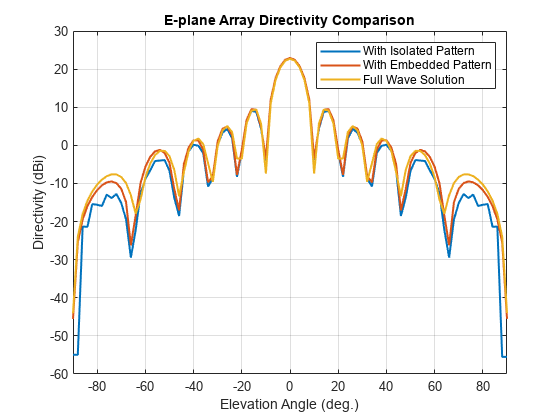
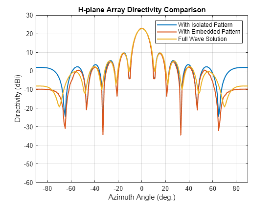
Calculate the pattern in the elevation plane (specified by azimuth = 0 deg and also called the E-plane) and azimuth plane (specified by elevation = 0 deg and called the H-plane) for the three arrays based on the isolated element pattern, the embedded element pattern, and the full-wave model.
Eplane1 = pattern(myURA1,freq,0,el);
Eplane2 = pattern(myURA2,freq,0,el);
[Eplane3,~,el3e] = pattern(myFullWaveArray,freq,0,el);
figure
plot(el,Eplane2,el,Eplane1,el3e,Eplane3,LineWidth=1.5);
axis([min(el) max(el) -60 30])
grid on
xlabel("Elevation Angle (deg.)");
ylabel("Directivity (dBi)");
title("E-plane Array Directivity Comparison")
legend("With Isolated Pattern","With Embedded Pattern","Full Wave Solution")
drawnow
Hplane1 = pattern(myURA1,freq,az/2,0);
Hplane2 = pattern(myURA2,freq,az/2,0);
Hplane3 = pattern(myFullWaveArray,freq,az/2,0);
figure
plot(az/2,Hplane2,az/2,Hplane1,az/2,Hplane3,LineWidth=1.5);
axis([min(az/2) max(az/2) -60 30])
grid on
xlabel("Azimuth Angle (deg.)");
ylabel("Directivity (dBi)");
title("H-plane Array Directivity Comparison")
legend("With Isolated Pattern","With Embedded Pattern","Full Wave Solution")
drawnow
The array directivity is approximately 23 dBi. This result is close to the theoretical calculation for the peak directivity [5] after taking into account the absence of a reflector, D = 4 / , .
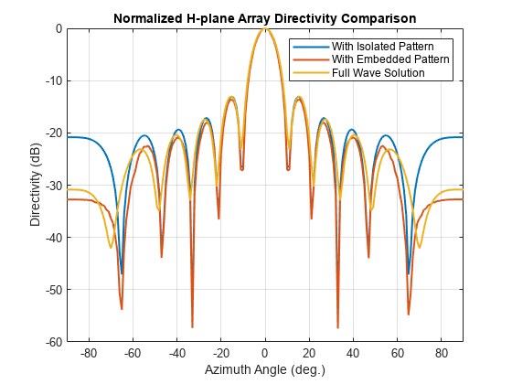
Normalize the directivity for the three arrays and plot it for comparison.
figure
Eplanenormlz1 = Eplane1 - max(Eplane1);
Eplanenormlz2 = Eplane2 - max(Eplane2);
Eplanenormlz3 = Eplane3 - max(Eplane3);
plot(el,Eplanenormlz2,el,Eplanenormlz1,el,Eplanenormlz3,LineWidth=1.5);
axis([min(el) max(el) -60 0])
grid on
xlabel("Elevation Angle (deg.)");
ylabel("Directivity (dB)");
title("Normalized E-plane Array Directivity Comparison")
legend("With Isolated Pattern","With Embedded Pattern","Full Wave Solution")

drawnow
figure
Hplanenormlz1 = Hplane1 - max(Hplane1);
Hplanenormlz2 = Hplane2 - max(Hplane2);
Hplanenormlz3 = Hplane3 - max(Hplane3);
plot(az/2,Hplanenormlz2,az/2,Hplanenormlz1,az/2,Hplanenormlz3,LineWidth=1.5);
axis([min(el) max(el) -60 0])
grid on
xlabel("Azimuth Angle (deg.)");
ylabel("Directivity (dB)");
title("Normalized H-plane Array Directivity Comparison")
legend("With Isolated Pattern","With Embedded Pattern","Full Wave Solution")
drawnow
The pattern comparison suggests that the main beam and the first side lobes are aligned for all three cases. Moving away from the main beam shows the increasing effect of coupling on the side lobe level. As expected, the embedded element pattern approach suggests a coupling level in between the full-wave simulation model and the isolated element pattern approach.
Comparison with 25-by-25 Array
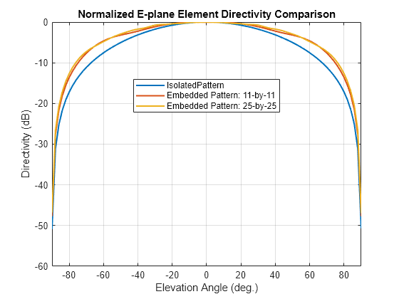
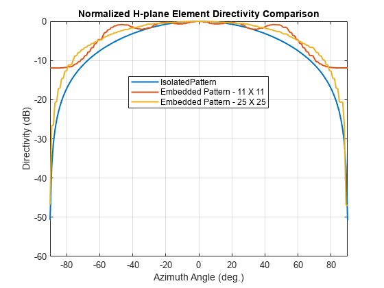
The behavior of the array pattern is intimately linked to the embedded element pattern. To understand how the choice of a 11-by-11 array impacts the center element behavior, increase the array size to a 25-by-25 array (12.5-by-12.5 aperture size). Note that the triangular mesh size for the full wave Method of Moments (MoM) analysis with 625 elements increases to 25000 triangles (40 triangles per dipole) and the computation for the embedded element pattern takes approximately 12 minutes on a 2.4 GHz machine with 32 GB memory. This time can be reduced by lowering the mesh size per element by meshing manually using a maximum edge length of .
load dipolearray
embpattern = 20*log10(DipoleArrayPatData.ElemPat);
EmbAnt2 = clone(EmbAnt);
EmbAnt2.AzimuthAngles = DipoleArrayPatData.AzAngles;
EmbAnt2.ElevationAngles = DipoleArrayPatData.ElAngles;
EmbAnt2.MagnitudePattern = embpattern;
Eplane1 = pattern(EmbAnt2,freq,0,el);
Eplane1 = Eplane1 - max(Eplane1);
Eplane2 = pattern(mydipole,freq,0,el);
Eplane2 = Eplane2 - max(Eplane2);
embpatE = pattern(EmbAnt,freq,0,el);
embpatE = embpatE - max(embpatE);
figure
plot(el,Eplane2,el,embpatE,el,Eplane1,LineWidth=1.5);
axis([min(el) max(el) -60 0])
grid on
xlabel("Elevation Angle (deg.)");
ylabel("Directivity (dB)");
title("Normalized E-plane Element Directivity Comparison")
legend("IsolatedPattern","Embedded Pattern: 11-by-11","Embedded Pattern: 25-by-25",Location="best")
drawnow
Hplane1 = pattern(EmbAnt2,freq,0,az/2);
Hplane1 = Hplane1 - max(Hplane1);
Hplane2 = pattern(mydipole,freq,0,az/2);
Hplane2 = Hplane2 - max(Hplane2);
embpatH = pattern(EmbAnt,freq,az/2,0);
embpatH = embpatH - max(embpatH);
figure
plot(az/2,Hplane2,az/2,embpatH,az/2,Hplane1,LineWidth=1.5);
axis([min(el) max(el) -60 0])
grid on
xlabel("Azimuth Angle (deg.)");
ylabel("Directivity (dB)");
title("Normalized H-plane Element Directivity Comparison")
legend("IsolatedPattern","Embedded Pattern: 11-by-11","Embedded Pattern: 25-by-25",Location="best")
drawnow
The plot above reveals that the difference between embedded element patterns of the 11-by-11 and the 25-by-25 array, respectively, is less than 0.5 dB, in the E-plane. However, the H-plane shows more variation for the 11-by-11 array as compared with the 25-by-25 array.
Scan Behavior and Embedded Element Pattern
Scan the array based on the embedded element pattern in the elevation plane defined by azimuth = 0 deg and plot the normalized directivity. Also, overlay the normalized embedded element pattern. Note the overall shape of the normalized array pattern approximately follows the normalized embedded element pattern. This is also predicted by the pattern multiplication principle.
eplane_indx = find(az==0);
scan_el1 = -30:10:30;
scan_az1 = zeros(1,numel(scan_el1));
scanEplane = [scan_az1;scan_el1];
hsv = phased.SteeringVector;
hsv.SensorArray = myURA1;
hsv.IncludeElementResponse = true;
weights = step(hsv,freq,scanEplane);
legend_string1 = cell(1,numel(scan_el1)+1);
legend_string1{end} = "Embedded element";
scanEPat = nan(numel(el),numel(scan_el1));
for i = 1:numel(scan_el1)
    scanEPat(:,i) = pattern(myURA1,freq,scan_az1(i),el,Weights=weights(:,i)); % -23.13;
    legend_string1{i} = strcat("scan = ",num2str(scan_el1(i)));
end
scanEPat = scanEPat - max(max(scanEPat));
figure
plot(el,scanEPat,LineWidth=1.5);
hold on
grid on
plot(el,embpatE,'-.',LineWidth=1.5);
axis([min(el) max(el) -50 0])
xlabel("Elevation (deg.)")
ylabel("Directivity (dB)")
title("E-plane Scan Comparison")
legend(legend_string1,Location="southeast")
hold off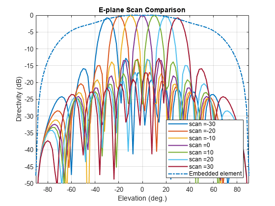
drawnow
Scan Blindness
In large arrays, it is possible that the array directivity to reduce drastically at certain scan angles. At these scan angle, referred to as the blind angles, the array does not radiate the power supplied at its input terminals [3]. Two common mechanisms under which blindness conditions occur are
Surface Wave Excitation
Grating Lobe Excitation
It is possible to detect scan blindness in large finite arrays by studying the embedded element pattern (also known as array element pattern in the infinite array analysis). The array being investigated in this example does not have a dielectric substrate/ground plane, and therefore the surface waves are eliminated. However, the grating lobe excitation mechanism can be investigated. To do so, increase the spacing across rows and columns of the array to be 0.7 . Since this spacing is greater than the half-wavelength limit, expect grating lobes in the visible space beyond a specific scan angle. As pointed out in [3], to accurately predict the depth of grating lobe blind angles in the finite array of dipoles, you need to have an array of the size 41-by-41 or higher. You compare 3 array sizes 11-by-11, 25-by-25, and 41-by-41 and check if the existence of blind angles can at least be observed in the 11-by-11 array. As mentioned earlier, the results were precomputed in Antenna Toolbox™ and saved in a MAT file. To reduce the computational time, the elements were meshed with maximum edge length of .
load dipolearrayblindness.mat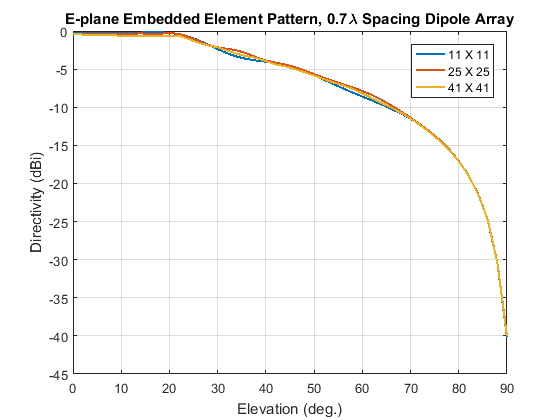
The normalized E-plane embedded element pattern for arrays of three sizes
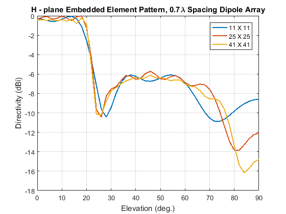
The normalized H-plane embedded element pattern for arrays of three sizes. Notice the blind angle around 24-26 deg.
Conclusion
The embedded element pattern approach is one possible way of performing the analysis of large finite arrays. They need to be so large that the edge effects can be ignored. The isolated element pattern is replaced with the embedded element pattern which includes the effect of mutual coupling.
Reference
[1] R. J. Mailloux, 'Phased Array Antenna Handbook', Artech House,2nd edition, 2005
[2] W. Stutzman, G. Thiele, 'Antenna Theory and Design', John Wiley & Sons Inc., 3rd Edition, 2013.
[3] R. C. Hansen, Phased Array Antennas, Chapter 7 and 8, John Wiley & Sons Inc.,2nd Edition, 1998.
[4] H. Holter, H. Steyskal, "On the size requirement for finite phased-array models," IEEE Transactions on Antennas and Propagation, vol.50, no.6, pp.836-840, Jun 2002.
[5] P. W. Hannan, "The Element-Gain Paradox for a Phased-Array Antenna," IEEE Transactions on Antennas Propagation, vol. 12, no. 4, July 1964, pp. 423-433.
See Also
Objects
dipole|rectangularArray|phased.URA(Phased Array System Toolbox) |phased.CustomAntennaElement(Phased Array System Toolbox) |phased.SteeringVector(Phased Array System Toolbox)