FIR Rate Conversion
Perform polyphase FIR sample rate conversion
Libraries:
DSP System Toolbox /
Filtering /
Multirate Filters
Description
The FIR Rate Conversion block performs an efficient polyphase sample rate conversion using a rational factor L/M along the first dimension. The block treats each column of the input as a separate channel and resamples the data in each channel independently over time.
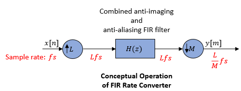
Conceptually, the rate converter combines an FIR interpolator followed by an FIR decimator.
The following schematic contains an upsampler, a combined anti-imaging and anti-aliasing
FIR filter, and a downsampler. To design an FIR filter which acts as a combined
anti-imaging and anti-aliasing FIR filter, use the designMultirateFIR function.
The rate converter does the following:
Upsamples the input to a higher rate by inserting L−
1zeros between input samples.Passes the upsampled data through an FIR filter.
Downsamples the filtered data to a lower rate by discarding M-
1consecutive samples following each sample that the block retains.

Note that the actual block algorithm implements a polyphase structure, an efficient equivalent of the combined system depicted in the diagram. For more details, see Algorithms.
Examples
Ports
Input
Output
Parameters
Block Characteristics
Data Types |
|
Direct Feedthrough |
|
Multidimensional Signals |
|
Variable-Size Signals |
|
Zero-Crossing Detection |
|
More About
Algorithms
The FIR rate converter is implemented efficiently using a polyphase structure.
To derive the polyphase structure, start with the transfer function of the FIR filter: This FIR filter is a combined anti-imaging and anti-aliasing filter.
N+1 is the length of the FIR filter.
You can rearrange this equation as follows:
L is the number of polyphase components, and its value equals the interpolation factor that you specify.
You can write this equation as:
E0(zL), E1(zL), ..., EL-1(zL) are polyphase components of the FIR filter H(z).
Conceptually, the FIR rate converter contains an upsampler, followed by a combined anti-imaging, anti-aliasing FIR filter H(z), which is followed by a downsampler.

Replace H(z) with its polyphase representation.

Here is the multirate noble identity for interpolation.

Applying the noble identity for interpolation moves the upsampling operation to after the filtering operation. This move enables you to filter the signal at a lower rate.

You can replace the upsampling operator, delay block, and the adder with a commutator switch. To account for the downsampler that follows, the switch moves in steps of size M. The switch receives the first sample from branch 0 and moves in the counter clockwise direction, each time skipping M−1 branches.
As an example, consider a rate converter with L set to 5 and M set to 3. The polyphase components are E0(z), E1(z), E2(z), E3(z), and E4(z). The switch starts on the first branch 0, skips branches 1 and 2, receives the next sample from branch 3, then skips branches 4 and 0, receives the next sample from branch 2, and so on. The sequence of branches from which the switch receives the data sample is [0, 3, 1, 4, 2, 0, 3, 1, ….].
The rate converter implements the L/M conversion by first applying the interpolation factor L to the incoming data, and using the commutator switch at the end to receive only 1 in M samples, effectively accounting for the downsampling factor M. Hence, the sample rate at the output of the FIR rate converter is Lfs/M.

References
[1] Orfanidis, Sophocles J. Introduction to Signal Processing. Upper Saddle River, NJ: Prentice-Hall, 1996.
Extended Capabilities
Version History
Introduced before R2006aSee Also
Functions
firceqrip|firgr|firnyquist
Objects
dsp.FIRRateConverter|dsp.FIRInterpolator|dsp.FIRDecimator|dsp.FIRHalfbandInterpolator|dsp.FIRHalfbandDecimator|dsp.CICCompensationInterpolator|dsp.CICCompensationDecimator


