Build, Verify, and Deploy Applications for Brake Control System
R2026bThis example shows how to build, verify, deploy, and run a system of brake control system software applications designed using the Software Component Designer app on a Linux development computer. You configure, build, and verify generated code for software component models, each representing an application, in the context of the Software Component Designer. Then, you deploy and run the applications in a Linux target environment by using the Linux Runtime Manager.
Open and Learn About the Example Models
If the software architecture model SWArch is not already open, open it. The model was developed with the Software Component Designer. To use the Software Component Designer, install the Software Component Designer for Simulink Support Package (see Install Software Component Designer for Simulink Support Package).
When you open a Simulink model in the Software Component Designer app, the software automatically maps the model to a software component and configures the model for application development and deployment to an Embedded Linux platform. For each software component model in the architecture model, the code generator produces:
Algorithm code and service interface code for connecting to service code that runs in the target environment
A
mainfunction that includes code for schedulingService implementation code that is integrated with the
mainfunctionCode for handling communication between applications and the operating system
To learn more about the example architecture model and its software component models, see Model and Simulate Services of Brake Control System.
Open the architecture model SWArch. It consists of four software component models, each representing an application.
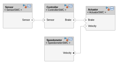
Configure Software Component Models for Code Generation and Deployment
When you open a software component or architecture model created with the Software Component Designer, the model opens with a configuration that supports the Embedded Linux target platform. For example, in the Configuration Parameters dialog box, the designer specifies these default model configuration parameter settings for the architecture model and the four software component models:
Hardware board is
None.System target file is set to
ert.tlc.Language is set to
C++.Language standard is set to
C++14 (ISO).Generate code only is cleared.
Package code and artifacts is cleared.
Toolchain is set to
Automatically locate an installed toolchain on a Linux system, and is set to CMakewhen you open a component model for the first time on a Windows system.Build configuration is set to
Faster builds.
The default setting for the Toolchain parameter is applied only when your platform choice (Embedded Linux or AUTOSAR Adaptive) changes. Other parameter settings that you save for a model are preserved
Alternative Hardware board settings are:
Embedded Coder Linux Docker Containerto deploy on x86_64 target hardware types running the Windows or Linux operating system..Embedded Coder Linux Docker Container-ARM64to deploy on ARM® target hardware types
You must compile application code intended to run on the Embedded Linux or AUTOSAR Adaptive platform on a Linux system. Options include compiling on a remote Linux development computer or an instance of Windows Subsystem for Linux that is running an SSH server.
The settings for parameters Language and Language standard are not configurable.
On the Solver pane, these parameters are set to default values that enable code generation:
Type is set to
Fixed-step.Solver is set to
discrete (no continuous states).
The setting for Type is not configurable.
If the SWArch model is not open, open it in the Software Component Designer app.
To see model configuration parameter settings for the architecture model:
On the toolstrip, click the Modeling tab.
Expand the Design section.
Under Design, click Model Explorer.
In the Model Explorer window, in the Model Hierarchy pane, expand the
SWArchnode.Click Configurations.
In the Contents pane, right-click Configuration (Active). Then, in the context menu, click Open.
For each software component model, open the model Configuration Parameters dialog box to browse through the parameter settings.
Right-click the software component model.
In the context menu, under Reference Component, click the Open as Top Model icon.
On the toolstrip, click the Modeling tab.
Click Model Settings. Then, in the menu, select Model Settings. The Configuration Parameters dialog box for the software component model opens.
Browse through the model settings.
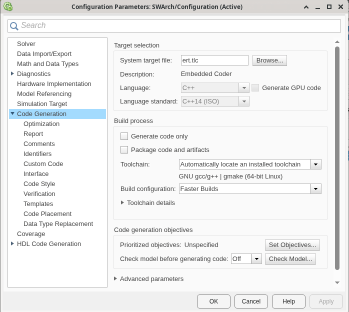
For more configuration parameter information, see Configure Software Component Models for Code Generation, Builds, and Deployment. For comprehensive information on model configuration, see .
Configure Services and Application Middleware for Code Generation
The next step for preparing an architecture model and its components for code generation is to configure services and the middleware for application-level communication.
Configure Services
For each software component model, determine whether you need to adjust service property settings for code generation. Service properties appear in the Property Inspector. For component models, you can focus on adjusting property settings for code generation by using the Service Mappings Editor.
Review the code generation settings for the software component models in this example.
In the architecture model, double-click the
Sensorcomponent model.Open the Service Mappings editor. On the Software Component Designer toolstrip, click Service Mappings. The editor appears under the model canvas.
Explore the Sensor component service mappings. The component uses a sender service to send queued distance data to the
Controllercomponent. In the Service Mappings editor, click the Senders tab. Then, click the port elementSensor.Distance. The Sender Service column shows the service is configured to send queued data, which is the default. The alternative is for the service to send the latest value.Click the Measurements tab. The sensor component uses a unit delay.The Measurement Service column shows the state of the delay is not measured.
Explore service mappings for the
Controllercomponent. The component uses a receiver service to receive queued distance data and a status value from the Sensor component. In the Service Mappings editor, click the Receivers tab. Then, click the port elementSensor.Distance. The Receiver Service column shows the service is configured to receive queued data, which is the default. The Status Element column shows the status port elementSensor.Distance_status. The status value returned is an enumerated value of typeSlSignalStatus, which is an enumeration of typeSlSignalStatusthat indicates whether send operations are successful or an error condition occurs.Explore service mappings for the Speedometer component. The component uses a server service to provide velocity data to the
Actuatorcomponent. In the Service Mappings editor, click the Servers tab. The server provides the velocity with the Simulink functiongetCurrentVelocity.Explore service mappings for the
Actuatorcomponent. The component receives queued data from theControllercomponent, using the port elementbrake.brakeCmd, and uses a client service to get the velocity on the function port elementVelocity.getCurrentVelocity. The service is configured to wait on server results before calling the server.
For more information about service mappings and using the Service Mappings editor, see Service Mappings Editor and Configure Model Elements with Service Interface Definitions for Code Generation.
Configure Middleware
To configure the middleware that an application uses for communicating with other applications:
Return focus to the architecture model.
On the Software Component Designer toolstrip (Software Component tab), in the Generate Code section, under Middleware, select
DDSorSOME/IP. This example uses DDS.
For more information about DDS, see https://www.omg.org/omg-dds-portal/.
Check Software Component Models for Conditions That Can Produce Undesirable Code
Use the Model Advisor to check the software component models for conditions, such as modeling patterns and configuration settings, that can cause the code generator to produce undesirable code.
For this example, run the Model Advisor on models SensorSWC, ControllerSWC, SpeedometerSWC, and ActuatorSWC. For each software component model:
1. From the architecture model, open a component model. Right-click the component model. Then, click the Open as Top Model icon.
2. Open the Model Advisor. On the toolstrip, click the Modeling tab. Then, click Model Advisor.
3. Select relevant code generation checks from the By Product node. In the Check Selector pane, clear the By Task node, clear and expand the By Product node, and select and expand the Embedded Coder node. Then, clear the selection of these irrelevant checks:
Component Deployment Guidelines for Data Interface
Check for missing error ports in AUTOSAR receiver interfaces
Check configuration for component deployment using service interface configuration
Check startup and shutdown event
4. Run the selected checks. Click the product name Embedded Coder. Then, on the toolstrip, click Run. The Model Advisor generates a report for the model. Some model configuration parameter warnings are reported. You can choose to change the parameter settings. This report shows the warnings removed.
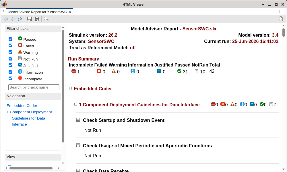
For more information about using the Model Advisor and the Embedded Coder Model Advisor checks, see and Check Your Model Using the Model Advisor.
Build Application Code
Start an application build. Then, use the Code view to examine some areas of the generated code.
Start Build
In the Software Component Designer, return focus to the architecture model SWArch. Then, do the following depending on the operating system of your development computer:
Linux operating system
On the Software Component Designer toolstrip, in the Code Generation menu, click
Build.
Windows operating system, option 1
Select model configuration parameter Generate code only. The Software Component Designer selects the parameter automatically when the Toolchain parameter is set to
CMake.On the Software Component Designer toolstrip, in the Code Generation menu, click
Generate Code.Relocate the generated source code to a remote Linux development computer.
On the remote Linux development computer, build applications.
Windows operating system, option 2
Set model configuration parameter Hardware Board to
Embedded Coder Linux Docker Container.Use the Linux Runtime Manager to establish a connection with a remoteLinux development computer or use Windows Subsystem for Linux (WSL).
On the Software Component Designer toolstrip, in the Code Generation menu, click
Build.
For more information about build options, see Application Build Configuration and Startup.
Key Folders and Files
The build process places and names generated files in a default folder and file structure. For the most comprehensive build process, building an application in the context of a system, the code generator creates a folder that has the name of the architecture model for storing component execution scheduling and service instance configuration manifest files. The manifest files are organized in a folder for each application (software component). For this example, the folder structure is:
SWArch
  Actuator
  Controller
  Sensor
  Speedometer
For each software component model in the architecture model, the code generator creates a folder in your MATLAB® current folder for storing files that it generates for the application. Paths for folders and files that you might want to explore are:
application/application- Build configuration files, such asbuildinfo.matand code descriptorcodedescriptor.dmr, and the algorithm and service interface source (.cpp) and header (.h) filesapplication/application/lib- Algorithm library and data filesapplication/exe- Executable program file and Make, data, and library files for building the executableapplication/services-Service implementation code.
The files application/application/application.h and application/application/application.cpp declare and define entry-point functions for the algorithm code, which get called from application code. For this example model, the entry-point functions include:
ActuatorSWC
ActuatorSWC_initializeActuatorSWC_terminateActuatorSWC_OnBrakeCommand (exported)
ControllerSWC
ControllerSWC_initializeControllerSWC_stepControllerSWC_terminate
SensorSWC
SensorSWC_initializeSensorSWC_stepSensorSWC_terminate
SpeedometerSWC
SpeedometerSWC_initializeSpeedometerSWC_terminateSpeedometerSWC_Task_200ms(exported)SpeedometerSWC_getCurrentVelocity(exported)
These functions exchange data with target application code through service interfaces. The files application/application/application_services.h are header files that declare interfaces that the generated algorithm entry-point functions use to call platform services.
For more information about the generated folder and file structure, see Build Application Code.
Examine Generated Code in Code View
The Code view in the Software Component Designer:
Shows generated code and overlays coverage results.
Provides coverage visualization, including annotations for coverage objectives, colors to indicate completeness, and tooltips that explain metrics.
Provides model-to-code navigation.
When you use the Code view to view code generated from the context of an architecture model, the Code view menu lists files that are relevant to the model visible in the Software Component Designer model canvas.
If you have not already done so, build the code for the component models in architecture model
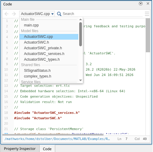
SWArch.In the Code pane, open the navigation menu by clicking the down arrow. As this figure shows, after a build of an architecture model, initially Code view lists component links, which you can use to open the software component models, and the software component model manifest files.
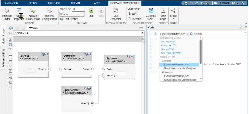
3. Click the ActuatorSWC component link. The menu lists files generated for that software component model. For a component model, Code view lists:
main file
Model files
Shared files
Service files
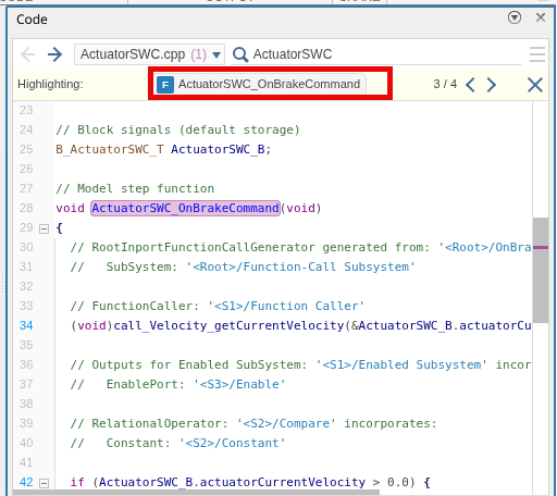
4. Use the search field to find the code for entry-point function ActuatorSWC_OnBrakeCommand.
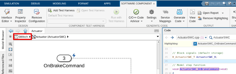
5. Change the focus of the navigation pane to another model. In the model canvas navigation bar, click SWArch. The Code view navigation pane displays the links for the components. Then, click the link for the component of interest.
Review Code Generation Reports
You can create a code generation report for a software component model by selecting model configuration parameter Create code generation report before building the model. When you build code for application deployment from an architecture model, the code generator produces a report for component models that have this parameter selected. To display the component reports as part of the build process, select parameter Open report automatically.
By default, the code generator provides access to generated files in a navigation pane and links to these sections in the report:
Summary (lists model and code information and if configured a link to a Model Advisor report)
Application Interface Report
Application Configuration and Execution
Subsystem Report
Code Interface Report
Traceability Report
Static Code Metrics Report
Code Replacements Report
Coder Assumptions
Create a report for software component model SensorSWC.
If the architecture model
SWArchis not open, open it in the Software Component Designer app.Right-click the software component model
SensorSWC.In the context menu, under Reference Component, click the Open as Top Model icon.
On the toolstrip, click the Modeling tab.
Click Model Settings. Then, in the menu, select Model Settings. The Configuration Parameters dialog box for the software component model opens.
Select Create code generation report and Open report automatically.
Save the model, and close the model window.
In the model window showing model
SWArchin the Software Component Designer app, on the toolstrip, click Generate Code and select Build. The code generator creates and opens the report during the build process.Explore the report content.
For more information, see Generate and Review Application Build Reports, Reports for Code Generation, and Generate Code Generation Report.
Verify Generated Application Code
After you generate code for each application, use available tools to verify the code.
To test numerical equivalency between software component model simulation and the generated code, you can run software-in-the-loop (SIL) and processor-in-the-loop (PIL) simulations on the component models.
Tools are also available for:
Code execution-time profiling
Code stack usage profiling
Code coverage during SIL or PIL simulation
Code analysis and tracing
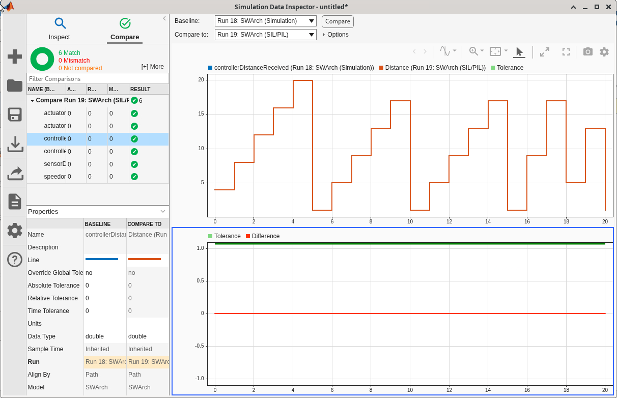
For this example, on a Linux system, in System Composer, you use the SIL/PIL Manager to verify numerical equivalency of normal and SIL simulations of the ControllerSWC component model. You configure the SIL/PIL Manager to run a normal mode simulation, run a SIL mode simulation, and then compare and display the results in the Description.
1. If the architecture model SWArch is not open, open it in the Software Component Designer app.
2. From within the SWArch model, on the Model block referencing the component model ControllerSWC, set the model block parameter Simulation mode to Software-in-the-loop (SIL).
3. Open the SIL/PIL Manager app. Click the Apps tab and search for SIL/PIL Manager. A SIL/PIL tab appears.
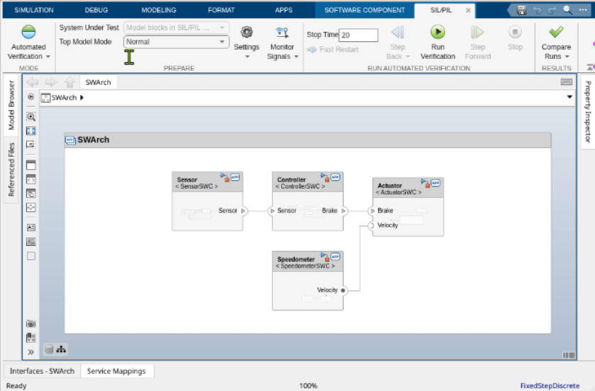
4. On the SIL/PIL Manager toolstrip, from the Automated Verification menu, select Automated Verification.
5. Click Run Verification. The SIL/PIL Manager builds code from the model, if necessary, runs a normal mode simulation, runs a SIL simulation, and compares and displays the results in the Simulation Data Inspector:
If you choose to configure the example model for development on a Windows system, for each component model, select model configuration parameter Use portable word sizes. When you select this parameter:
64-bit integers use the correct primitive C data type for the context in which the code is compiled.
The code is compiled for the development computer by using the toolchain that is linked to the selected MEX compiler, regardless of the setting for model configuration parameter Toolchain.
An alternative to using the SIL/PIL Manager is to use a test harness model to simulate software component models in the context of an architecture model for Model block SIL simulations. If you have a Simulink Test™ license, you can use the to create a test harness from a component model. See Create or Import Test Harnesses and Select Properties (Simulink Test) (Simulink Test).
For more information about SIL simulation, see Configure and Run SIL Simulation.
Deploy and Run Applications
You can build, package, deploy, and run a service-oriented application code by using the Embedded Coder Support Package for Service-Oriented Applications on Linux. For information on how to install the support package, see .
This example shows how to use the Linux Runtime Manager, which is available in the support package, to deploy applications to a Docker container running on an ARM64 Linux target computer. Make configuration and setup adjustments if you are using an alternative supported target computer.
1. On your development computer, delete the generated folder slprj, the folders generated for each software component model (Actuator, Controller, Sensor, and Speedometer), and the model.slxc files. Set up your hardware board. For the architecture model and the software component models, the Runtime Manager changes the Hardware board configuration parameter setting to Embedded Coder Linux Docker Container-ARM64, and rebuilds the application executable programs for that target environment.
2. Address target computer requirements, such as the installation of required software and configuration of network and SSH ports (see Target Computer Requirements).
3. Open the Linux Runtime Manager app.
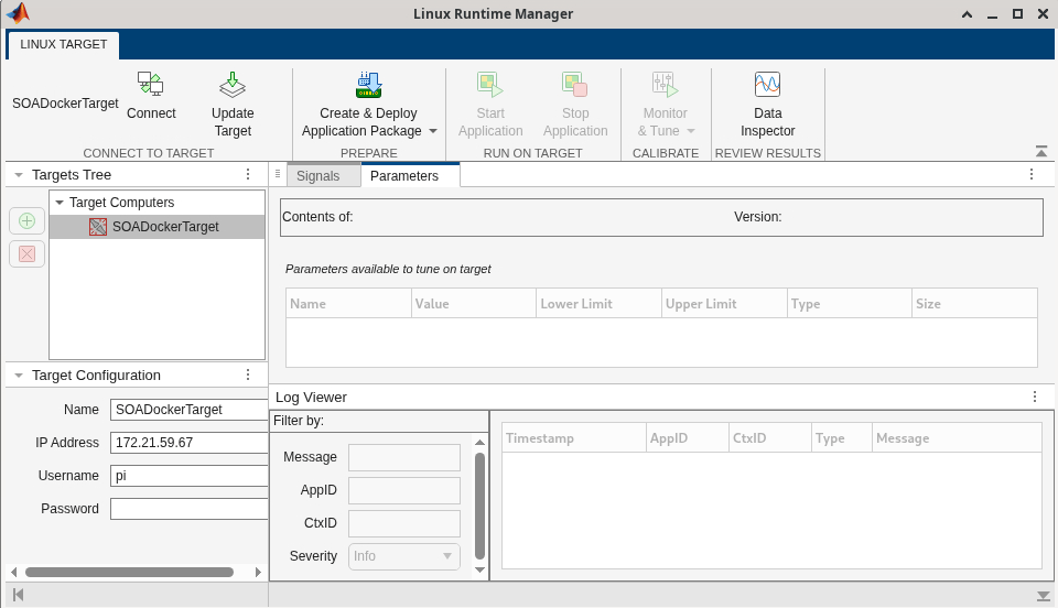
4. Add your target computer to the Targets Tree pane and configure the computer. In the Runtime Manager, in the Targets Tree pane, click Target Computers. Then, click the plus button. To configure the target computer, specify a name and the IP address, and enter the user name and password to connect to the Linux target computer. See Configure a Target Computer.
5. Connect the development and target computers. In the Targets Tree pane, select your target name. Then, on the toolstrip, click Connect.
6. In the dialog box that appears, enter the path for the location where you want the Runtime Manager to deploy applications.
7. Build the application code. For the architecture model and each software component model, on the toolstrip, from the Create & Deploy Application Package menu, select Create. A dialog box appears. Select the architecture model SWArch and click Open. The Runtime Manager checks whether model configuration parameters Hardware board and Toolchain have the required settings for the target computer. If they do not have the required settings, the tool informs you of the recommended changes. If you click Continue, for each software component model, the Runtime Manager builds an executable program.
8. Create an application package and deploy the application to the target computer. On the Runtime Manager toolstrip, from the Create & Deploy Application Package menu, select Deploy. In the dialog box that appears, select the SWArch.mldatx file. The deployed package appears in the Targets Tree pane.
9. Start the system of applications. In the Targets Tree pane, under Target Computers > target-computer-name, select architecture-model-name (for example, SWArch). Then, on the toolstrip, click Start Application.
If you are interested in calibrating sensor application data, see for information on setting up a Universal Measurement and Calibration Protocol (XCP) service for that application and Calibrate Service-Oriented Application for information on calibration.

