Synthesize Generated HDL Code from MATLAB Algorithms
Once you have generated HDL code from your compatible MATLAB® algorithm with HDL Coder™, you can use HDL Coder to optimize your design for speed and area, and to facilitate FPGA synthesis, implementation, and programming.
This example shows how to synthesize generated HDL code for a MATLAB algorithm. In this example, you use a MATLAB algorithm that models a simple up counter. This counter is compatible with HDL code generation. To learn more about how to make a MATLAB algorithm compatible with HDL code generation, see Create HDL- or HLS-Compatible MATLAB Algorithms.
In this example, you:
Set up a third-party synthesis tool.
Create a MATLAB HDL Coder project.
Generate HDL code from the MATLAB algorithm.
Synthesize the generated HDL code using a third-party synthesis tool and analyze the result.
To synthesize HDL code from a Simulink model, see HDL Code Generation and FPGA Synthesis from Simulink Model.
Set Up Synthesis Tool Path
First, set up a third-party synthesis tool by using hdlsetuptoolpath to define
the path to the third-party synthesis tool executable. This example uses
AMD®
Vivado®.
Install AMD Vivado. To check your installation, launch AMD Vivado by entering
!vivadoin the MATLAB Command Window. If you open AMD Vivado to check your installation, close the application without saving.Use
hdlsetuptoolpathto set up your third-party synthesis tool with MATLAB. In the MATLAB Command Window, use this command, and replace theToolNameandToolPathwith your synthesis tool and synthesis tool installation path:
hdlsetuptoolpath('ToolName','Xilinx Vivado','ToolPath',...
 'C:\Xilinx\Vivado\2024.1\bin\vivado.bat');
For more information on supported third-party tools and hardware, see HDL Language Support and Supported Third-Party Tools and Hardware.
MATLAB Counter Algorithm
Open this example to obtain the MATLAB counter function and test bench for this tutorial.
open mlhdlc_counter
open mlhdlc_counter_tb
The MATLAB function mlhdlc_counter is a model of a 4-bit synchronous up counter. When the input argument, enable_ctr, is a nonzero value, the persistent variable, count_val, increases by one. The value of count_val increases by one until the count reaches 15. Then the counter returns to zero. To learn more about this function and the associated test bench, see Create HDL- or HLS-Compatible MATLAB Algorithms.
Create a MATLAB HDL Coder Project
To create a MATLAB HDL Coder project:
In the MATLAB Editor, in the Apps tab, select HDL Coder. In the MATLAB HDL Coder Project window, set Name to
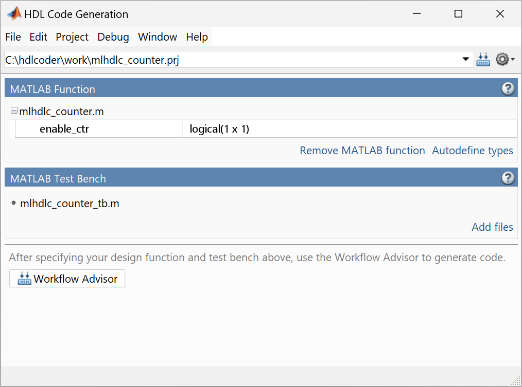
mlhdlc_counter. Set Location to the current working directory. HDL Coder creates themlhdlc_counter.prjproject in the specified directory.In the HDL Code Generation window, in the MATLAB Function section, click Add MATLAB function and select the function file for the up counter algorithm,
mlhdlc_counter.m. In the MATLAB Test Bench section, click Add files and add the MATLAB test bench,mlhdlc_counter_tb.m.You must add a MATLAB test bench unless the design does not need fixed-point conversion and you do not want to generate a register transfer level test bench.
Note
Add only the top-level MATLAB function. Do not use spaces in file names or paths to prevent code generation failures.
In the MATLAB Function section, click Autodefine types and then click Run. HDL Coder infers the input types by executing the MATLAB test bench. Click Use These Types to use the recommended types for the MATLAB design. If you do not add a test bench, you must define the inputs to the top-level MATLAB function. For more information, see Specify Properties of Entry-Point Function Inputs.
Click Workflow Advisor.
Generate HDL Code
Use the Workflow Advisor to generate HDL code for FPGA synthesis:
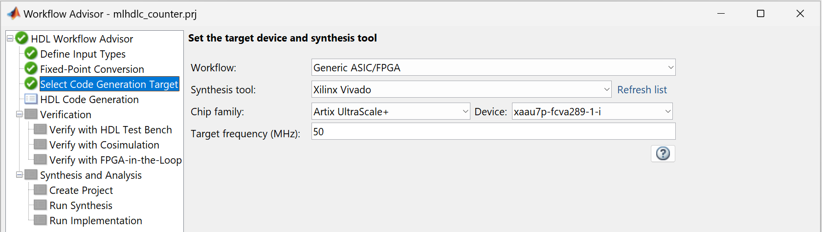
In the Workflow Advisor, click the Select Code Generation Target task.
Set Synthesis tool to
Xilinx Vivado.Set Target Frequency (MHz) to 50.
Right-click HDL Code Generation and select Run to Selected Task.
Perform FPGA Synthesis and Analysis
Use the Workflow Advisor to facilitate synthesis, implementation, and analyze the generated code.
In the Workflow Advisor, right-click the Synthesis and Analysis > Run Implementation task and select Run to Selected Task.
HDL Coder runs these tasks to generate HDL code for the algorithm:
In the Create Project task, the third-party synthesis tool creates a synthesis project for the HDL code.
In the Run Synthesis task, HDL Coder launches the third-party synthesis tool in the background. The third-party synthesis tool opens the synthesis project, compiles the HDL code, synthesizes the design, and generates the netlists, area, and timing reports.
In the Run Implementation task, HDL Coder launches the third-party synthesis tool in the background. The third-party synthesis tool places and routes the design for the specified hardware and generates pre- and post-route timing information for critical path analysis.
Click the Run Implementation task. In the bottom right
pane, scroll to the top and click post_synth_report.html to
view the place and route report.
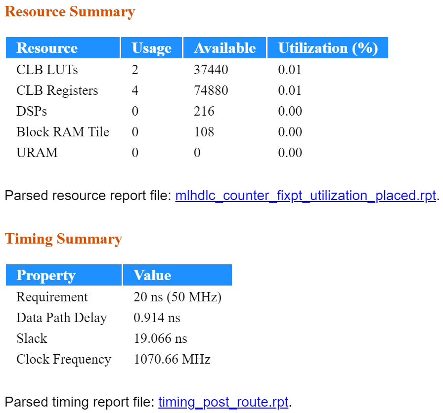
The Resource Summary section shows that 0.02% of the FPGA is in use.
In the Timing Summary section, a positive slack indicates that the data propagates through a path faster than required, with time left over.
If your design does not meet timing or resource constraints, use speed and area optimizations in HDL Coder to meet these requirements, respectively. To learn more, see Introduction to Optimizations in HDL Coder.