Verify Generated HDL Code from Simulink Model
This example shows how to generate an HDL test bench and verify the generated code for a simple counter model. To generate HDL code for this model, see Generate HDL Code from Simulink Model. If you have not generated HDL code for this model, HDL Coder™ runs code generation before generating the testbench.
What Is an HDL Test Bench?
To verify the functionality of the HDL code for the DUT, generate a HDL test bench. A test bench includes:
Stimulus data generated by signal sources connected to the entity under test.
Output data generated by the entity under test. During a test bench run, this data is compared to the outputs of the VHDL® model for verification.
Clock, reset, and clock enable inputs to drive the entity under test.
A component instantiation of the entity under test.
Code to drive the entity under test and compare its outputs to the expected data.
You can simulate the generated test bench and script files by using the Siemens® ModelSim™ simulator.
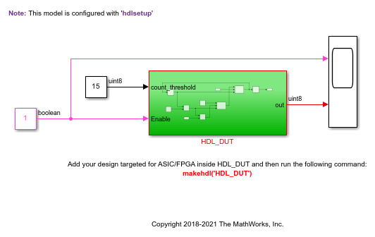
Simple Counter Model
This model counts up from zero to a threshold value of 15, then wraps back to zero. You can change the threshold value by changing the value of the Constant block connected to the count_threshold port. The Enable port specifies whether the counter counts upward or holds the previous value. You can change the counter action by changing the value of the Constant block connected to the Enable port. A value of 1 indicates that the counter counts upward. A value of 0 holds the previous count value.
Verification Methods
If you have HDL Verifier™ installed, you can also verify the generated HDL code by using these methods.
| Verification Method | For More Information |
|---|---|
| HDL Cosimulation | Cosimulation |
| SystemVerilog DPI Test Bench | SystemVerilog DPI Test Bench |
| FPGA-in-the-Loop | FPGA-in-the-Loop |
Generate HDL Test Bench
Generate VHDL, Verilog®, or SystemVerilog test bench code as applicable. By default, the HDL code and the
test bench code are written to the same target folder hdlsrc
relative to the current folder.
For the counter model, the HDL_DUT subsystem is the DUT. To
generate the testbench, select this subsystem.
In the Apps tab, select HDL Coder.
Select the DUT subsystem,
HDL_DUT, and make sure this name appears in the Code for option on the HDL Code tab. To remember the selection, pin this option. Click Generate Testbench.
Generate Verilog Test Bench Code
To generate Verilog testbench code for the counter model:
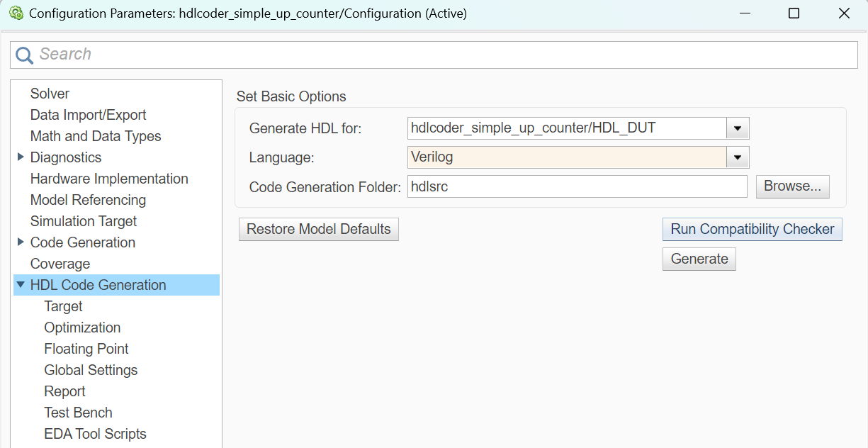
In the HDL Code tab, click Settings.
In the HDL Code Generation pane, for Language, select
Verilog.In the HDL Code Generation > Test Bench pane, click Generate Test Bench.
HDL Coder compiles the model and generates the test bench.
Test bench generation is completed and displays this message. The
generated files appear in the hdlsrc folder.
### HDL TestBench Generation Complete.
View HDL Test Bench Files
For the counter model, the hdlsrc folder contains these
test bench files.
HDL_DUT_tb.vhd— VHDL test bench code containing generated test and output data. If you generated Verilog or SystemVerilog test bench code, the generated files areHDL_DUT_tb.vorHDL_DUT_tb.sv.HDL_DUT_tb_pkg.vhd— Package file for VHDL test bench code. If you generated SystemVerilog test bench code, the generated file isHDL_DUT_tb_pkg.sv. This file is not generated if you specified Verilog as the target language.HDL_DUT_tb_compile.do— Siemens ModelSim compilation script (vcomcommands). This script compiles and loads the entity to be tested (HDL_DUT.vhd) and the test bench code (HDL_DUT_tb.vhd).HDL_DUT_tb_sim.do— Siemens ModelSim script to initialize the simulator, set up wave window signal displays, and run a simulation.
To view the generated test bench code in the MATLAB® Editor, double-click the HDL_DUT_tb.vhd or
HDL_DUT_tb.v file in the current folder.
Run Simulation and Verify Generated HDL Code
To verify the simulation results, you can use these HDL simulators:
Siemens ModelSim Simulator
Xilinx® Vivado® Simulator
Using ModelSim Simulator
You must have already installed Siemens
ModelSim Simulator. To open the simulator, use the vsim (HDL Verifier) function. This command shows how to
open the simulator by specifying the path to the
executable:
vsim('vsimdir','C:\Program Files\ModelSim\questasim\10.6b\win64\vsim.exe')
To compile and run a simulation of the generated model and test bench
code, use the HDL Coder generated scripts. For the counter model, run these commands
to compile and simulate the generated test bench for the
HDL_DUT Subsystem.
Open the Siemens ModelSim software and navigate to the folder that has the generated code files and the scripts.
Use the generated compilation script to compile and load the generated model and text bench code. For the
HDL_DUTsubsystem, run this command to compile the generated code.QuestaSim>do HDL_DUT_tb_compile.do
Use the generated simulation script to execute the simulation. You can ignore warning messages. For the
HDL_DUTSubsystem, run this command to simulate the generated code.QuestaSim>do HDL_DUT_tb_sim.do
The simulator optimizes your design and displays the results in a wave window. if you don't see the simulation results, open the wave window. The simulation script displays inputs and outputs in the model including the clock, reset, and clock enable signals in the wave window.

You can now view the signals and verify that the simulation results match the functionality of your original design. After verifying, close the Siemens ModelSim simulator, and then close the open files in the MATLAB Editor.
Using Vivado Simulator
You must have already installed Xilinx Vivado Simulator. To test your design with Xilinx Vivado Simulator:
Set the tool path to Xilinx Vivado by using the
hdlsetuptoolpathfunction. For more information, see Set Up Xilinx Vivado.In the Configuration Parameters window, click HDL Code Generation > Test Bench and set Simulation tool to
Xilinx Vivado Simulator.Generate HDL code and a test bench for your Simulink model. The following simulation script files are generated for the
HDL_DUTsubsystem and are compatible with Xilinx Vivado Simulator:HDL_DUT_compile.tcl– Compilation script to compile and load the generated modelHDL_DUT_tb_compile.tcl– Compilation script to compile and load the generated test benchHDL_DUT_tb_sim.tcl– Simulation script to execute the simulation
Run this command in the MATLAB Command Window to compile the generated code with Xilinx Vivado Simulator.
!vivado -mode batch -source HDL_DUT_tb_compile.tclRun this command to simulate the generated code.
!vivado -mode batch -source HDL_DUT_tb_sim.tclAfter the script runs a message appears in the MATLAB Command Window to indicate whether the test passed or failed.
Deploy Generated HDL Code on Target Device
To deploy the generated code on a target FPGA device, use the Simulink® HDL Workflow Advisor. See HDL Code Generation and FPGA Synthesis from Simulink Model.
See Also
Functions
Model Settings
- HDL test bench | Cosimulation model | SystemVerilog DPI test bench | Simulation tool | HDL code coverage