Usage of Rate Change and Constant Blocks
You can follow these guidelines to learn how to use blocks that can perform rate conversions in your model and blocks from the Sources library such as Constant blocks in your design. Each guideline has a severity level that indicates the level of compliance requirements. To learn more, see HDL Modeling Guidelines Severity Levels.
Usage of Rate Conversion Blocks
Guideline ID
2.5.1
Severity
Recommended
Description
There are various ways in which you can model rate transitions. How you model rate transitions determine the timing and resource requirements of your design. This guideline shows various approaches for modeling rate transitions.
Increasing the Sample Rate
This table illustrates the blocks that you can use to increase the sample rate of your design. When you use these blocks, leave the block parameters to the default settings.
Rate Conversion Approach
| Block | Generates Bypass Register? | Generates Zero Padding? | Notes |
|---|---|---|---|
| Repeat (DSP System Toolbox) | No | No | To use this block, you must have DSP System Toolbox™ installed. |
| Rate Transition | No | No | None |
| Upsample (DSP System Toolbox) | Yes | Yes | To use this block, you must have DSP System Toolbox installed. When you use this block, consider the impact of the bypass register and the logic that inserts zero padding on hardware resource usage. |
For the Rate Transition block, to upsample the input signal without incurring a unit delay, in the Block Parameters dialog box of the Rate Transition block:
Clear the Ensure data integrity during data transfer check box.
Clearing this check box makes the Ensure deterministic data transfer (maximum delay) check box to disappear.
Configure the output port sample time of the block to be an integer multiple of the input port sample time. Specify a fractional value of
1/nfor Sample time multiple wherenis an integer. You can choose any value for the block parameter Output port sample time options as long as Sample time multiple uses a value1/n.
When the input and output clocks are not synchronous to each other, to avoid insertion of a bypass register in the HDL code generated for the Repeat and Rate Transition blocks, insert one unit delay following the Repeat and Rate Transition blocks in your model.
You can use the Initial Condition parameter of the block when increasing the sample rate. This parameter is used for upsampling when you leave the Ensure data integrity during data transfer check box selected. The initial value is propagated to the generated HDL code for the state that is created from a Rate Transition block.
Decreasing the Sample Rate
To reduce the sample rate, you can use a Downsample (DSP System Toolbox) or a Rate Transition block. To use the Downsample block, you must have DSP System Toolbox installed. When you use these blocks, leave the block parameters to the default settings.
When downsampling the input signal, use the Rate Transition block because you can leave the block parameters to the default settings for HDL code generation. The Ensure data integrity during data transfer and Ensure deterministic data transfer (maximum delay) check boxes must be left selected. This mode generates an additional bypass register in the HDL code.
You can use the Initial Condition parameter of the block when decreasing the sample rate. When downsampling, this parameter is implemented as a bypass register and is not seen because it passes from the input to the output at initial clock cycle. The initial value is propagated to the generated HDL code for the state that is created from a Rate Transition block.
Use Discrete and Finite Sample Time for Constant Block
Guideline ID
2.5.2
Severity
Recommended
Description
By default, the Sample time parameter of a Constant block is
inf. When you use the Constant block, set
the Sample time to -1. To identify
Constant blocks that have infinite sample time in your
design, in the Simulink® model window, In the Debug tab, on the Information Overlays > Sample Time section, select Colors.
If you enable optimizations that add or handle latency in your design, such as
streaming, sharing, clock-rate pipelining, or delay balancing, and then generate
HDL code, HDL Coder™ resolves the sample times of Constant blocks with
Sample time set to inf, if the
sample times do not propagate to the device under test (DUT) output. For
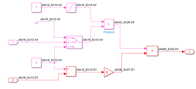
example, in this model DUT, you can generate HDL code with optimizations that
add latency because the Product block merges the
Constant and Ground blocks that have infinite
sample times into a signal that has a fixed sample time, before to the DUT
output. The Sample Time Legend displays the infinite sample times in pink and
the fixed sample times in red.

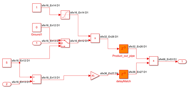
When the HDL block property OutputPipeline of the
Product block is 3 and you generate HDL
code and a generated model, the generated model shows the infinite sample times
resolved to fixed sample times with the output pipeline delays applied and the
balanced delays applied on the other signal path.

For blocks that have inf sample times propagate to the DUT
output, you can identify and change the sample time of the blocks to
-1 by using either of these approaches:
Run a script that can programmatically change the sample time of the blocks to
-1. For an example script, see Identify and Programmatically Change and Display HDL Block Parameters.Run the check Check for infinite and continuous sample time sources in the HDL Code Advisor. If running the check fails, it displays sources such as Constant blocks that have infinite sample time. Select Modify Settings to update the sample time to
-1or to inherit via backpropagation.
Dynamically Change Sample Offset for Downsample Block
Guideline ID
2.5.3
Severity
Informative
Description
You can use the Sample offset parameter to adjust the sample offset for the Downsample (DSP System Toolbox) block. However, when you set the offset using this block parameter, the sample offset cannot be changed dynamically during simulation.
To change the sample offset for the Downsample block dynamically, you can adjust the sample offset for the input signal using the Simulink block instead of the Sample offset parameter.
This figure shows a model for a dynamically changing sample offset of the Downsample block by using HDL Counter and Switch blocks. The model uses HDL Counter block with the reset signal to latch the input signal at the desired downsampling period. Adjust the sample offset by varying the reset timing of the counter. In this model, a Delay block connects to the output port to suppress the generation of bypass registers.

You can also use a Rate Transition block in place of the Downsample block if you do not have the DSP System Toolbox for using Downsample block.