Generate IP Core from Frame-Based Model with AXI4 Stream Video Interface
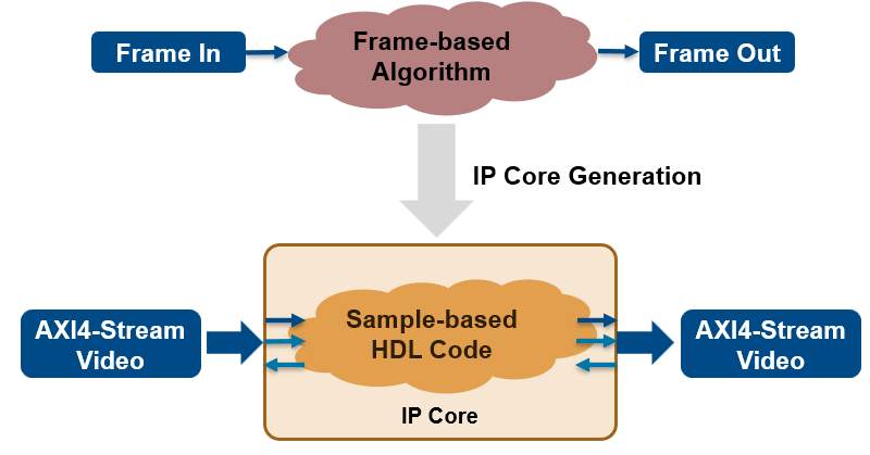
You can use the HDL Coder™ frame-to-sample optimization to design and deploy frame-based algorithms that use AXI4-Stream Video interfaces to enable high-speed video streaming.

In this example, you:
Model a frame-based edge detection algorithm by using neighborhood processing functions.
Generate an HDL IP core with an AXI4-Stream Video interface.
Integrate the generated IP core into a Xilinx® Zynq® ZC706 reference design with access to HDMI interfaces.
Prerequisites
To run this example, you must have the following software and hardware board setup:
Xilinx Vivado® Design Suite
Xilinx Zynq ZC706 evaluation kit with FMC HDMI I/O card (FMC-HDMI-CAM or FMC-IMAGEON)
Set Up Hardware
1.Install the HDL Coder Support Package for AMD FPGA and SoC Devices, and SoC Blockset™ Support Package for AMD® FPGA and SoC Devices. To install the support packages, in MATLAB®, in the Home tab, click Add-Ons > Get Hardware Support Packages.
2. Use the SD card image provided by the HDL Coder Support Package for AMD FPGA and SoC Devices.
3. Set up the Xilinx Zynq ZC706 board and the FMC HDMI I/O card as shown in the figure below. Follow these instructions for connecting the hardware:
Remove the SD card from the host computer and insert it into the Zynq board.
Plug the HDMI FMC card into the FMC connector on the Zynq board.
Connect an Ethernet cable to the board.
Connect the power cable.
Connect an HDMI video source to the FMC HDMI I/O card. The video source must be able to provide 1080p video output, such as a video camera, smart phone, tablet, or the HDMI output of your computer.
Connect a monitor to the FMC HDMI I/O card. The monitor must be able to support 1080p display.
To learn more about the ZC706 hardware setup, see Xilinx ZC706 Evaluation Board User Guide.

Model a Frame-Based Algorithm to Integrate with the Default Video System Reference Design
Open the frame-based model, hdlcoder_frame_video_edge,which contains an edge detection and image overlay algorithm in the device under test (DUT), EdgeDUT.
load_system('hdlcoder_frame_video_edge')
open_system('hdlcoder_frame_video_edge/EdgeDUT')

In the example model, the DUT subsystem, hdlcoder_frame_video_edge/EdgeDUT, uses the hdl.npufun function to implement the Sobel edge detection algorithm and the code.hdl.pipeline function to pipeline the design to achieve the frequency needed to perform edge detection on live video. For more information on modeling the algorithm, see Synthesize Code for Frame-Based Model. When using the frame-to-sample optimization, you do not need to model additional control signals. The ports ImageIn and Overlay are the pixel data ports for video streams. The additional input ports, cThreshold and cAlpha, are control ports that adjust the parameters of the Sobel edge detection algorithm. You can enable the frame-to-sample conversion for this model using these commands:
hdlset_param('hdlcoder_frame_video_edge','FrameToSampleConversion','on');
hdlset_param('hdlcoder_frame_video_edge/EdgeDUT/ImageIn','ConvertToSamples','on');
Generate HDL IP Core with AXI4-Stream Video Interface
When you generate an IP core that is integrated into the Default Video System Reference Design, the video stream signals are encoded into a 32-bit representation 32’hFFRRGGBB. To account for the data format, the subsystem hdlcoder_frame_video_edge/EdgeDUT/IntensityCalculator decodes the RGB 32-bit representation of the video stream to get the intensity of the frame. Additionally, the subsystem encodes the output into the same format when it calculates the overlay. For more information on the architecture of the reference design see Default Video System Reference Design.
To generate an IP core with the AXI4-Stream Video interface from a frame-based model:
1. Set up the Xilinx Vivado synthesis tool path by using the hdlsetuptoolpath command. Use your own Vivado installation path when you run the command.
hdlsetuptoolpath('ToolName','Xilinx Vivado','ToolPath',vivadopath);
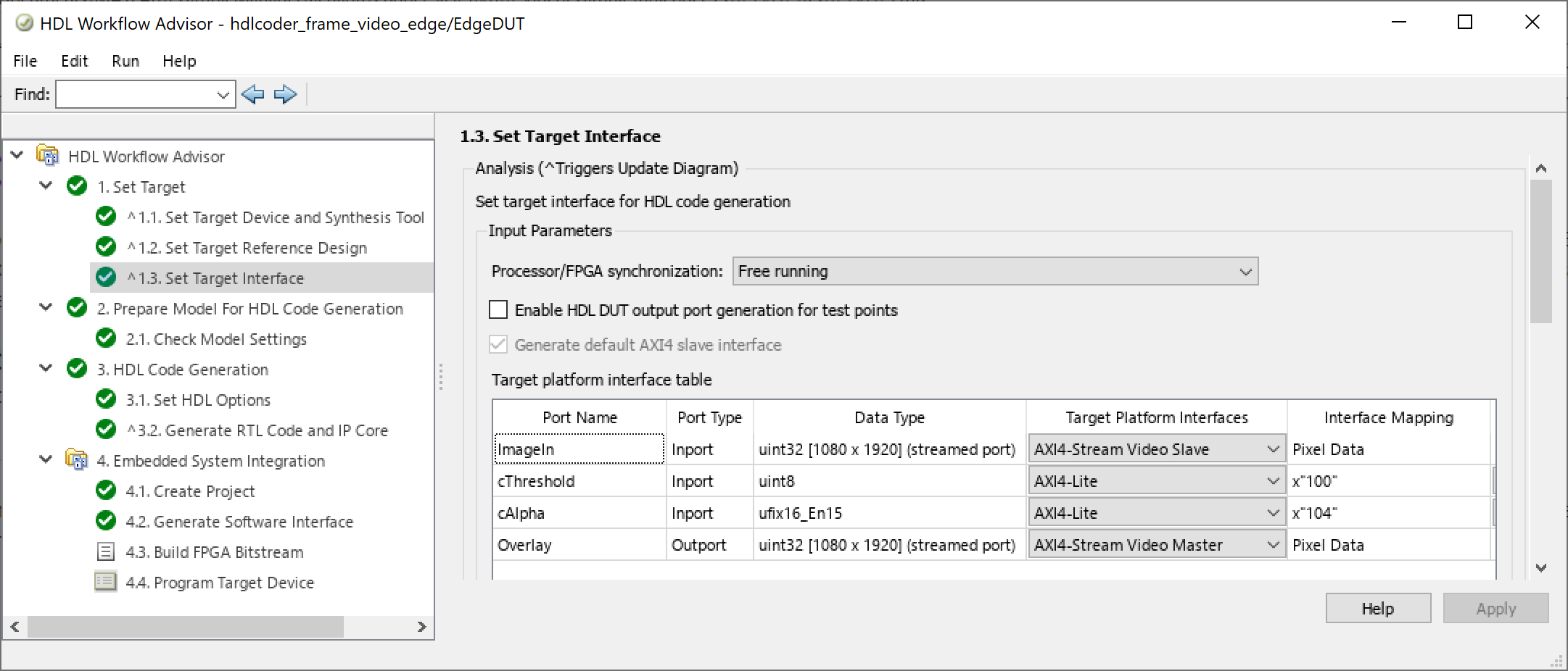
2. In the 1.1 Set Target Device and Synthesis Tool Task, set Target workflow to IP Core Generation and set Target platform to Xilinx Zynq ZC706 evaluation kit. In task 1.2, set the Reference Design to Default video system (requires HDMI FMC module). In task 1.3, Target Platform Interface Table section, set the cells to these settings:

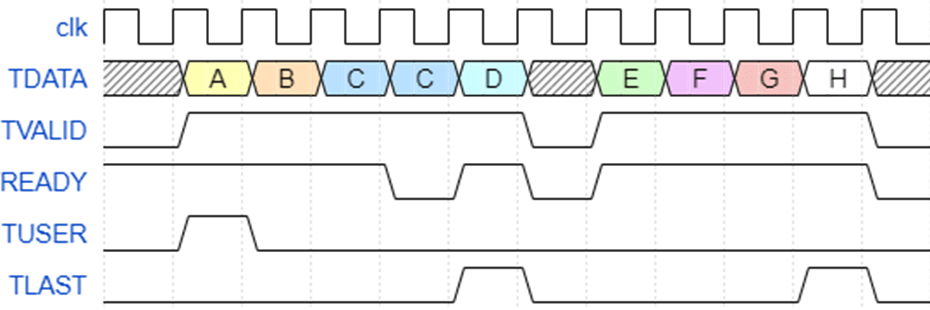
The AXI4-Stream video interface contains data (TDATA) and control signals such as TVALID, back pressure (READY), and data boundary (TDATA and TLAST). TDATA indicates the start of a video frame and TLAST indicates the end of a line. The timing diagram shows the timing for a 2x4 frame.

To use the frame-to-sample optimization, you must map your frame inputs and outputs as Pixel Data. The TVALID, READY, and TLAST control signals are automatically generated. In this example, the frame ports ImageIn and Overlay are mapped to the AXI4-Stream Video interface. The scalar ports cAlpha and cThreshold are mapped to the AXI4-Lite interface. HDL Coder generates AXI4 interface accessible registers for these ports.
3. Right-click task 3.2, Generate RTL Code and IP Core, and select Run to Selected Task to generate the IP core. You can find the register address mapping and other information for the IP core in the generated IP Core Report.
4. Right-click task 4.2 Build FPGA Bitstream, and select Run to Selected Task to generate the Vivado project and build the FPGA bitstream.
5. Run task 4.3, Program Target Device, to program the FPGA board.
System Architecture with the Generated IP Core
The high-level architecture of the complete Zynq design is shown below.

The generated DUT IP core is integrated into the Default Video System reference design. The AXI4-Stream Video interface processes the video stream from the HDMI input and sends the output video stream to the HDMI output. The host computer can tune parameters by writing to AXI4-Lite registers within the algorithm IP core.