Main Content

compare

Compare identified model output with measured output

Description

Plot Simulated and Measured Outputs

compare(data,sys) simulates the response of a single dynamic system model sys or an array of dynamic system models, and superimposes the response for each model over the plotted input/output measurement data contained in data. data can be a timetable, a comma-separated input/output matrix pair, or a data object such as an iddata object or an idfrd object.

The plot also displays the normalized root mean square (NRMSE) measure of the goodness of the fit between the simulated response and the output measurement data.

Use this function when you want to validate a single model or when you want to evaluate a set of candidate models identified from the same measurement data.

For timetables and data objects, compare matches the input/output channels based on the channel names in sys and ignores nonmatching channels.

compare(data,LineSpec) also specifies the line type, marker symbol, and color for the model response.

compare(data,sys1,...,sysN) compares the responses of multiple dynamic systems on the same axes. compare automatically chooses the line specifications.

example

compare(data,sys1,LineSpec1,...,sysN,LineSpecN) compares the responses of multiple systems on the same axes using the line type, marker symbol, and color specified for each system.

example

Predict Model Output

compare(___,kstep) predicts the response of sys, using a prediction horizon specified by kstep. Prediction uses output measurements as well as input measurements to project a future response. kstep represents the number of time samples between the timepoint of each output measurement and the timepoint of the resulting predicted response.

For more information on prediction, see Simulate and Predict Identified Model Output. You can use this syntax with any of the previous input/output combinations.

example

Specify Additional Options

compare(___,opt) configures the comparison using an option set. Options include initial condition handling, data offsets, and data selection.

example

Return Results

[ymod,fit,ic] = compare(___) returns the model response ymod, goodness of fit value fit, and the initial conditions ic. This syntax does not generate a plot, so any line specifications are ignored.

example

Examples

collapse all

Identify a linear model and visualize the simulated model response with the data from which it was generated.

Load the input/output measurements in tt1, and identify a third-order state-space model sys.

load sdata1 tt1;
sys = ssest(tt1,3);

sys is a continuous-time identified state-space (idss) model.

Use compare to simulate the sys response and plot it alongside the data in tt1.

figure
compare(tt1,sys)

Figure contains an axes object. The axes object with ylabel y contains 2 objects of type line. These objects represent Validation data (y), sys: 70.56%.

The plot illustrates the differences between the model response and the original data. The percentage shown in the legend is the NRMSE fitness value. It represents how close the predicted model output is to the data.

To change display options in the plot, right-click the plot to access the context menu. For example:

  • To plot the error between the predicted output and measured output, select Error Plot.

  • To view the confidence region for the simulated response, select Characteristics -> ConfidenceRegion.

  • To specify number of standard deviations to plot, double-click the plot and open the Property Editor dialog box. In the Options tab, specify the number of standard deviations in Confidence Region for Identified Models. The default value is 1 standard deviation.

Identify a linear model and visualize the predicted model response with the data from which it was computed.

Identify a third-order state-space model using the input/output measurements in umat1 and ymat1.

load sdata1 umat1 ymat1 Ts
sys = ssest(umat1,ymat1,3,'Ts',Ts);

sys is a discrete-time identified state-space (idss) model.

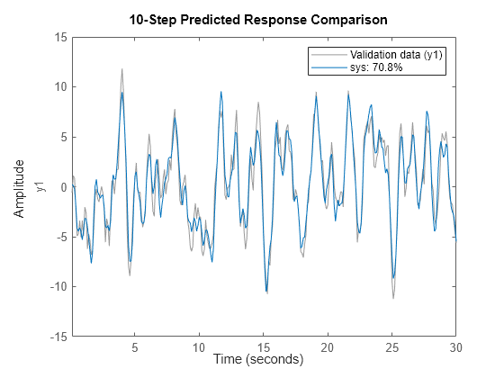
Now use compare to plot the predicted response. Prediction differs from simulation in that it uses both measured input and measured output when computing the system response. The prediction horizon defines how far in the future to predict, relative to your current measured output point. For this example, set the prediction horizon kstep to 10 steps, and use compare to plot the predicted response against the original measurement data.

kstep = 10;
compare(umat1,ymat1,sys,kstep)

Figure contains an axes object. The axes object with ylabel y1 contains 2 objects of type line. These objects represent Validation data (y1), sys: 70.8%.

In this plot, each sys data point represents the predicted output associated with output measurement data that was taken at least 10 steps earlier. For instance, the point at t = 15s is based on output measurements taken at or prior to t = 5s. The calculation of this t = 15s sys data point also uses input measurements up to t = 15s, just as a simulation would.

The plot illustrates the differences between the model response and the original data. The percentage shown in the legend is the NRMSE fitness value. It represents how closely the predicted model output matches the data.

To change display and simulation options in the plot, right-click the plot to access the context menu. For example, to plot the error between the predicted output and measured output, select Error Plot from the context menu. To change the prediction horizon value, or to toggle between simulation and prediction, select Prediction Horizon from the context menu.

Identify several model types for the same data, and compare the results to see which best fits the data.

Load the data, which contains iddata object z1 with single input and output.

load iddata1;

From z1, identify a model for each of the following linear forms:

  • ARMAX (idpoly) of orders 2, 3, and 1, with dead time of 0

  • State space (idss) with three states

  • Transfer function (idtf) with three poles

sys_armax = armax(z1,[2 3 1 0]);
sys_ss = ssest(z1,3);
sys_tf = tfest(z1,3);

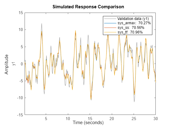
Using compare, plot the simulated responses for the three models with z1.

compare(z1,sys_armax,sys_ss,sys_tf)

Figure contains an axes object. The axes object with ylabel y1 contains 4 objects of type line. These objects represent Validation data (y1), sys\_armax: 70.27%, sys\_ss: 70.56%, sys\_tf: 70.96%.

For this set of data, along with the default settings for all the models, the transfer-function form has the best NRMSE fit. However, the fits for all models are within about 1% of each other.

You can interactively control which model responses are displayed in the plot by right-clicking on the plot and hovering over Systems.

Compare the outputs of multiple estimated models of differing types to measured frequency-domain data.

For this example, estimate a process model and an output-error polynomial from frequency response data.

load demofr  % frequency response data
zfr = AMP.*exp(1i*PHA*pi/180);  
Ts = 0.1;
data = idfrd(zfr,W,Ts);  
sys1 = procest(data,'P2UDZ'); 
sys2 = oe(data,[2 2 1]);

sys1, an idproc model, is a continuous-time process model. sys2, an idpoly model, is a discrete-time output-error model.

Compare the frequency response of the estimated models to data.

compare(data,sys1,'g',sys2,'r');

Figure contains 2 axes objects. Axes object 1 with title From: u1, ylabel To: y1 contains 3 objects of type line. These objects represent Data, sys1: 88.04%, sys2: 88.04%. Axes object 2 with ylabel To: y1 contains 3 objects of type line. These objects represent Data, sys1: 88.04%, sys2: 88.04%.

The two models have NRMSE fit values that are nearly equal with respect to the data from which they were calculated.

Modify default behavior when you compare an estimated model to measured data.

Estimate a transfer function for measured data.

load sdata1 tt1;
sys = tfest(tt1,3);

sys is a continuous-time identified transfer function (idtf) model.

Suppose you want your initial conditions to be zero. The default for compare is to estimate initial conditions from the data.

Create an option set to specify the initial condition handling. To use zero for initial conditions, specify 'z' for the 'InitialCondition' option.

opt = compareOptions('InitialCondition','z');

Compare the estimated transfer function model output to the measured data using the comparison option set.

compare(tt1,sys,opt)

Figure contains an axes object. The axes object with ylabel y contains 2 objects of type line. These objects represent Validation data (y), sys: 70.66%.

Load the data.

load iddata2 z2

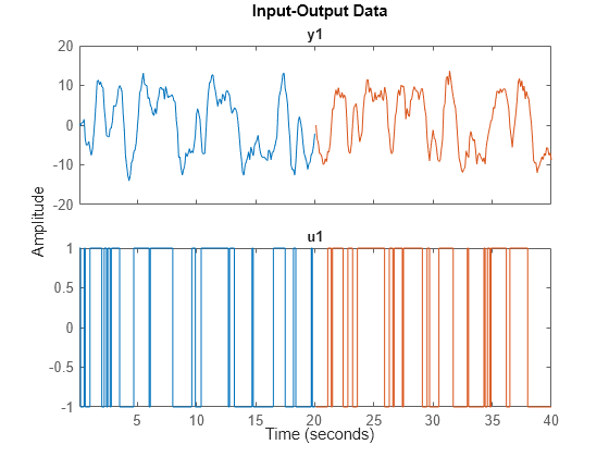
Split the data into estimation and validation sets.

z2e = z2(1:200);
z2v = z2(201:400);
idplot(z2e,z2v)

Figure contains 2 axes objects. Axes object 1 with title y1 contains 2 objects of type line. These objects represent z2e, z2v. Axes object 2 with title u1 contains 2 objects of type line. These objects represent z2e, z2v.

Estimate a state-space model and a transfer function model using the estimation data.

sys_ss = ssest(z2e,2);
sys_tf = tfest(z2e,2,1);

Use compare to obtain initial conditions ic_ss for sys_ss.

[y_ss,fit_ss,ic_ss] = compare(z2e,sys_ss);
ic_ss
ic_ss = 2×1

   -0.0018
    0.0016

ic_ss is a numeric vector of initial states.

Use compare to obtain initial conditions ic_tf for sys_tf.

[y_tf,fit_tf,ic_tf] = compare(z2e,sys_tf);
ic_tf
ic_tf = 
  initialCondition with properties:

     A: [2x2 double]
    X0: [2x1 double]
     C: [-1.6093 5.1442]
    Ts: 0

ic_tf is an initialCondition object that contains, in state-space form, a model of the free response of sys_tf to the initial conditions. A and C contain the free-response information and X0 contains the initial states.

Now obtain initial conditions for both models at once using the validation data.

[y_sstf,fit_sstf,ic_sstf] = compare(z2v,sys_ss,sys_tf);
ic_sstf
ic_sstf=2×1 cell array
    {2x1 double          }
    {1x1 initialCondition}

ic_sstf is a cell array that contains an initial state vector for sys_ss and an initialCondition object for sys_tf.

compare can provide initial conditions for an existing model with any measurement data set.

Input Arguments

collapse all

Validation data, specified as a timetable, a comma-separated matrix pair, a cell array, or a data object. The specification for data depends on the data type.

Timetable

For SISO, MISO, and MIMO systems, specify data as a timetable that uses a regularly spaced time vector. For the timetable data type, data contains variables representing the input and output channels.

data must have the same variable names as the original data from which each model sys was estimated. The model properties include the names of the input and output variables. You therefore do not need to explicitly specify which channels to use in the timetable.

For multiexperiment data, specify data as a 1-by-Ne cell array, where Ne is the number of experiments. The sample times of all the experiments must match.

Matrices

For SISO, MISO, and MIMO systems, specify data as a pair of matrices with dimensions Ns-by-Nu for the input matrix and Ns-by-Ny for the output matrix. The software uses the sample period in the Ts property of sys.

For multiexperiment data, specify data as a pair of 1-by-Ne cell arrays, where Ne is the number of experiments. The sample times of all the experiments must match the sample time of sys.

Data Object

Specify data as an iddata, idfrd, or frd model object.

If sys is:

  • A parametric model such as idss, then data can be an iddata, idfrd, or frd model object.

  • A frequency-response data model (either an idfrd, or frd model object), then data must also be a frequency-response data model.

  • An iddata object, then data must be an iddata object with matching domain, number of experiments and time or frequency vectors.

For examples, see:

.

For more information about working with estimation data types, see Data Domains and Data Types in System Identification Toolbox.

Identified model, specified as a dynamic system model, an iddata object, or a model array.

When the time or frequency units of data do not match the units of sys, compare rescales sys to match the units of data.

Prediction horizon, specified as one of the following:

  • Inf — Compare simulated response of sys to data.

  • Positive finite integer — Compare predicted response of sys to data, where each predicted response point is based not only on measured input data up to that timepoint, but also on measured output data up to kstep timepoints earlier.

compare ignores kstep when sys is an iddata object, an FRD model, or a dynamic system with no noise component. compare also ignores kstep when using frequency response validation data.

If you specify kstep that is greater than the number of data samples, compare sets kstep to Inf and provides a warning message.

For more information on simulation and prediction, see Simulate and Predict Identified Model Output.

For an example, see Compare Predicted Response of Identified Time-Domain Model to Measured Data.

Line style, marker, and color of both the line and marker, specified as a character vector, such as 'b' or 'b+:'.

For more information about configuring LineSpec, see the Linespec input argument of plot. For an example, see Compare Multiple Estimated Models to Measured Frequency-Domain Data.

Comparison options, specified as an option set you create using compareOptions.

Available options include:

  • Handling of initial conditions

  • Sample range for computing fit numbers

  • Data offsets

  • Output weighting

For examples, see:

Output Arguments

collapse all

Model response, returned as a timetable, a matrix, an iddata object, an idfrd object, a cell array, or an array. The output type depends on the models and data you provide, as follows:

  • For a single model and single-experiment data set, ymod is a timetable, a matrix, an iddata object, or idfrd object.

  • For multimodel comparisons, ymod is a cell array with one timetable, matrix, iddata object, or idfrd object entry for each input model.

  • For multiexperiment data, ymod is a cell array with one entry for each experiment.

  • For multimodel comparisons using multiexperiment data, ymod is an Nsys-by-Nexp cell array, where Nsys is the number of models, and Nexp is the number of experiments.

  • If sys is a model array, ymod is an array with an element corresponding to each model in sys and experiment in data. For more information on model arrays, see stack

If kstep is not specified or is Inf, then compare returns the simulated response in ymod.

Otherwise, compare returns the predicted response. Measured output values in data up to time tn-kstep are used to predict the output of sys at time tn. For more information on simulation and prediction, see Simulate and Predict Identified Model Output.

The compare response computation requires a specification for initial condition handling. By default, compare estimates the initial conditions to maximize the fit to data. See compareOptions for more information on how compare determines the initial conditions to use.

NRMSE fitness value indicator of how well the simulated or predicted model response matches the measurement data, returned as a vector, a matrix, or a cell array. The output depends on the models and data you provide, as follows:

  • If data is an iddata object, fit is a vector of length Ny, where Ny is the number of outputs

  • If data is an FRD model, fit is an Ny-by-Nu matrix, where Nu is the number of inputs in data

  • For a single model and single-experiment data set, fit is a vector or matrix

  • For multimodel comparisons, fit is a cell array with one entry for each input model

  • For multiexperiment data, fit is a cell array with one entry for each experiment

  • For multimodel comparisons using multiexperiment data, fit is an Nsys-by-Nexp cell array, where Nsys is the number of models, and Nexp is the number of experiments

  • If sys is a model array, fit is an array with an element corresponding to each model in sys and experiment in data

compare calculates fit (in percentage) using:

fit=100(1||yy^||||ymean(y)||),

where y is the validation data output and y^ is the output of sys.

For FRD models — compare calculates fit by comparing the complex frequency response. The fits of the magnitude and phase curves shown in the compare plot are not computed by compare separately.

Initial conditions used to compute system response, returned as an empty array, a vector, an initialCondition object, or a cell array.

For a single model and single-experiment data, the form of the output depends on the model type.

  • For state-space models, ic is a numeric vector that contains the initial states.

  • For transfer function and polynomial models, ic is an initialCondition object. An initialCondition represents, in state-space form, the free response of the model (A and C matrices) to the estimated initial states (x0).

  • When sys is an frd or iddata object, ic is the empty array [], because initial conditions cannot be used with these objects.

For multiple model and/or experiments, the form of the output is as follows:

  • For multimodel comparisons, ic is a cell or object array, with one vector, matrix, or initialCondition entry for each input model.

  • For multiexperiment data, ic is a cell or object array, with one entry for each experiment.

  • For multimodel comparisons using multiexperiment data, ic is an Nsys-by-Nexp cell or object array, where Nsys is the number of models and Nexp is the number of experiments.

  • If sys is a model array, ic is an array with an element corresponding to each model in sys and experiment in data.

By default, compare uses findstates to estimate the initial states in ic. To change this behavior, set the 'InitialCondition' option in opt (see compareOptions). If you have input/output history that immediately precedes your start point, you can set 'InitialCondition' to that history data. compare then uses data2state to compute the end state of the history data, and thus the start state for the simulation. Other choices include setting initial conditions to zero, or to specific values that you determine previously. For more information about finding initial conditions, see Estimate Initial Conditions for Simulating Identified Models.

If you are using an estimation model that does not explicitly use states, compare first converts the model to its state-space representation and then maps the data to the initial states. compare then packages the initial state vector and the A and C state-space matrices into an initialCondition object. For an example of using compare with such a model, see Obtain Initial Conditions.

Tips

  • The NRMSE fit result you obtain with compare may not precisely match the fit value reported in model identification. These differences typically arise from mismatches in initial conditions, and in the differences in the prediction horizon defaults for identification and for validation. The differences are generally small, and should not impact your model selection and validation workflow. For more information, see Resolve Fit Value Differences Between Model Identification and compare Command.

  • compare matches the input/output channels in data and sys based on the channel names. Thus, it is possible to evaluate models that do not use all the input channels that are available in data. This flexibility allows you to compare multiple models which were each identified independently from different sets of input/output channels.

  • The compare plot allows you to vary key parameters. For example, you can interactively control:

    • Whether you generate a simulated or predicted response

    • Prediction horizon value

    • Initial condition handling

    • Which experiment data you view

    • Which system models you view

    To access the controls, right-click the plot to bring up the options menu.

Version History

Introduced in R2006a

expand all