Create Field Points
Use the Optical Design and
Simulation Library for Image Processing
Toolbox™ to create light source representations using field points. For a given optical
system, you can programmatically create multiple field points, which represent light sources
at infinity or light sources at finite positions, using the fieldPoint
function.
You can also create field points interactively using the Optical System Designer app. For information on loading your optical system and creating field points in the Optical System Designer app, see Create Field Points in Optical System Designer.
Create Light Sources at Infinity
Create a light source located an infinite distance from the first component in the optical system at a specified angle from the optical axis. This figure shows a light source, at the field angle from the optical z-axis, located an infinite distance from the surface of a lens.
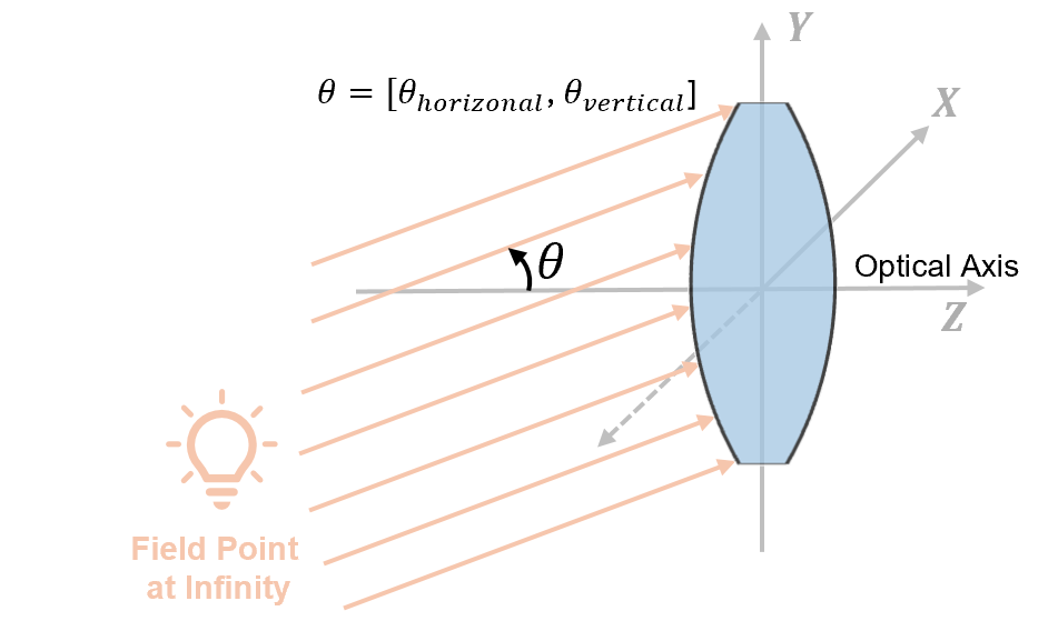
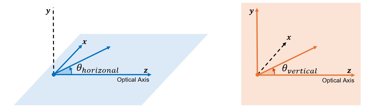
The field angle is defined by its horizontal and vertical components, and , respectively. These are the angles between the light rays and the optical z-axis in the yz-plane and in the xz-plane, respectively. This figure shows and in the local coordinate frame of the optical system. To learn more about optical coordinate systems, see Coordinate Systems in Optical Design.
To create a field point that represents a light source at infinity, use the
fieldPoint function and specify the angles input
argument. When you define a field point at infinity, the function creates a
FieldAngle
Create Light Sources at Finite Positions
Create light source representations at a finite distance from the first component in the
optical system. When you create a field point using the fieldPoint
object function, you can specify the reference frame for a light source at finite position
by using the ReferenceFrame
ReferenceFrame Value | Light Source Position | Code Example |
|---|---|---|
| Position specifies the light source in the global coordinate system. |
fp = fieldPoint(Position=[1 5 20],ReferenceFrame="Global"); |
| Position specifies the light source relative to a planar object in the object plane. |
fp = fieldPoint(Position=[1 5],ReferenceFrame="Object"); |
| Position specifies the light source relative to planar image formed in the image plane. |
fp = fieldPoint(Position=[0 10],ReferenceFrame="Image"); |
When you define a field point at a finite distance, the function creates a
FieldPosition
Light Source in Global Coordinate System
Create a field point that represents the light source position in the global coordinate system. The global reference frame aligns the origin and axes of the optical system coordinate frame with the global optical system. You must define the field point as a global (x, y, z) coordinate.
You can use the global field point reference frame to define a light source anywhere in space.
Light Source Relative to Object Plane
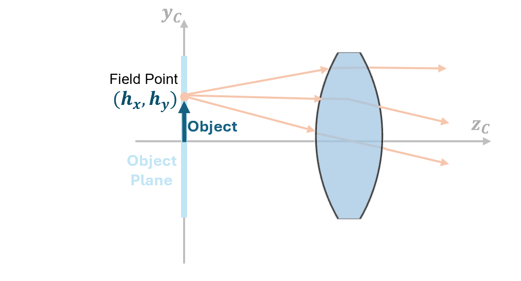
Create a field point relative to an object imaged in the object plane. You can specify the position that represents the dimensions of a planar object imaged at a finite location, such as a projector optical system. The coordinates of this position are of the form (hx, hy), and signify how far the field point is from the center of the object plane in the horizontal and vertical directions, respectively. This helps you describe where light from different parts of the object enters the optical system.
This image shows a 2-D representation of a field point that is positioned relative to the object plane, defined by the xc-, yc-, and zc-axes.
To create a field point relative to an object, the object plane of the optical system
must be located at a finite distance from the first component of the optical system. To
define the object plane position, specify the Position property of
the ObjectPlane
object. Then, set the object as the ObjectPlane property of the opticalSystem object.
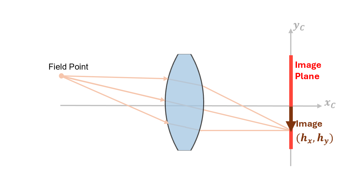
Light Source Relative to Image Plane
Create a field point that represents a light source such that the image forms at a specified location. You can specify the image location in the local coordinate system of the image plane of the optical system. The coordinates of this position are of the form (hx, hy), where hx and hy, and signify how far the field point is from the center of the image in the horizontal and vertical directions, respectively. This helps you describe where light from different parts of the image is focused after passing through the optical system.
This image shows a 2-D representation of a field point positioned relative to the image plane, defined by the xc-, yc-, and zc-axes.
Create Multiple Field Points
You can specify multiple field points located at both finite and infinite distances
relative to the optical system. Create multiple field points, as an array of
FieldAngle and FieldPosition objects, using these
steps.
Create any number of field points using the
fieldPointfunction. For example, create a field point at an infinite distance as aFieldAngleobject and three field points at finite distances asFieldPositionobjects.fp1 = fieldPoint(Angles=[-5 0]); fp2 = fieldPoint(Position=[0 10 -5],ReferenceFrame="Global"); fp3 = fieldPoint(Position=[0 5 -10],ReferenceFrame="Global"); fp4 = fieldPoint(Position=[0 -5],ReferenceFrame="Object");
Combine the four field points into an array.
fp = [fp1 fp2 fp3 fp4];
Perform ray tracing or analysis using the field point array. For example, to trace rays for an optical system
opsys, specify the field point array as theFieldPointname-value argument of thetraceRaysfunction.rays = traceRays(opsys,FieldPoint=fp);
Create Field Points in Optical System Designer
This section shows how to load an optical system and define the field points interactively in the Optical System Designer app. To get started with the Optical System Designer app, see Design Optical System Using Optical System Designer.
First, design or load your optical system from a ZMX file or the workspace. Run the
Simulate Ray Tracing Through Wide Angle Lens example and import the
optical system you create, opsys, into the Optical System
Designer app.
openExample("optics/SimulateRayTracingThroughWideAngleLensExample")Run the example. Then, open the Optical System Designer app.
opticalSystemDesigner;
To import the optical system from the workspace, select Import on the Optical System tab of the app
toolstrip, and select From Workspace. Then, in the dialog
box, select the opsys object from the menu to import the optical
system.
To define the light source using field points, on the Optical System tab of the app toolstrip, in the Light Source Editor section, select Light Source.
On the optical system visualization, the app marks the field point location using a colored dot. Next to it, the app depicts the field of view (FOV) as a conical shape, along with its corresponding angle value. In the Light Source Editor pane, you can add or remove field points, and enable or disable specific field points in the Field Point Editor.
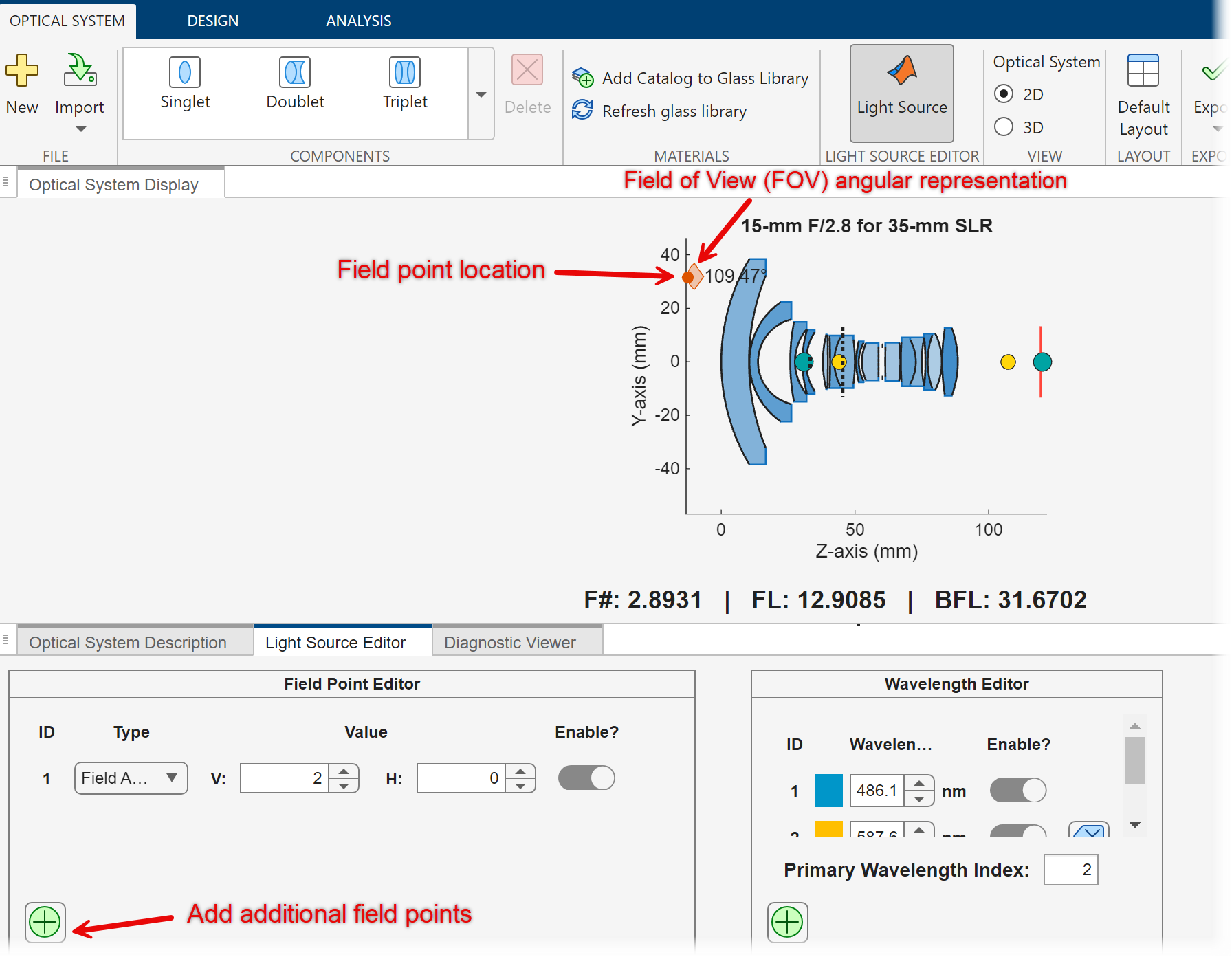
You can define field points using one of these options.
| Type | Value |
|---|---|
| Specify the V and H values, which correspond to the vertical and horizontal angles of the light source relative to the optical axis, respectively. Units are in degrees. |
| Specify the X and Y values, which correspond to the position, or the dimensions, of the planar image formed at the image plane. |
| Specify the X and Y values, which correspond to the position, or the dimensions, of a planar object imaged at a finite location. |
| Specify the X, Y, and Z values, which correspond to the X-, Y-, and Z-coordinates of the light source relative to the global reference frame. |
To learn more about optical system coordinate frames, see Coordinate Systems in Optical Design.