Coordinate Systems in Optical Design
Optical Design and Simulation Library for Image Processing Toolbox™ uses three distinct coordinate systems for defining the position and orientation of optical system components in space and relative to one another.
Global Coordinate System — A fixed world coordinate system in which all optical system components are placed.
Local Coordinate System — Local coordinate system that you can use to tune the position and angular orientation of each component or surface in the optical system. For example, you can tilt a component relative to the optical axis.
Construction Coordinate System — Construction coordinate system that you can use to tune the position and angular orientation of the next component in the optical system.
Global Coordinate System
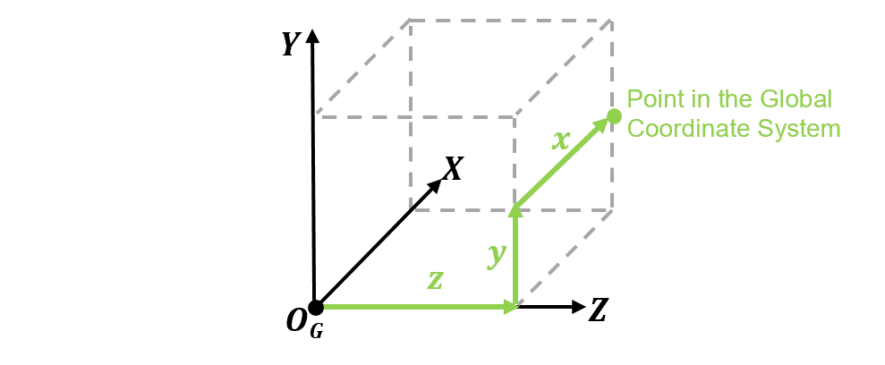
The global coordinate system is a reference coordinate system that serves as a common baseline for describing the positions and orientations of all optical components and elements within a system. It is defined by a set of axes, an origin point, and units. This coordinate system consists of three perpendicular X-, Y-, Z-axes. The units are in millimeters. The origin, OG, is a fixed point in space where, by default, the first surface or element is placed in an optical system. This image shows the global coordinate system in Cartesian coordinates that is used in optical system design.
Local Coordinate System
The local coordinate system is a coordinate system that is specific to an individual optical component or surface in the optical system. Use this coordinate system to fine-tune the position and angular orientation of each component or surface. Each local coordinate system is defined relative to a parent coordinate system, and therefore also to the global system.
Optical System Coordinate System
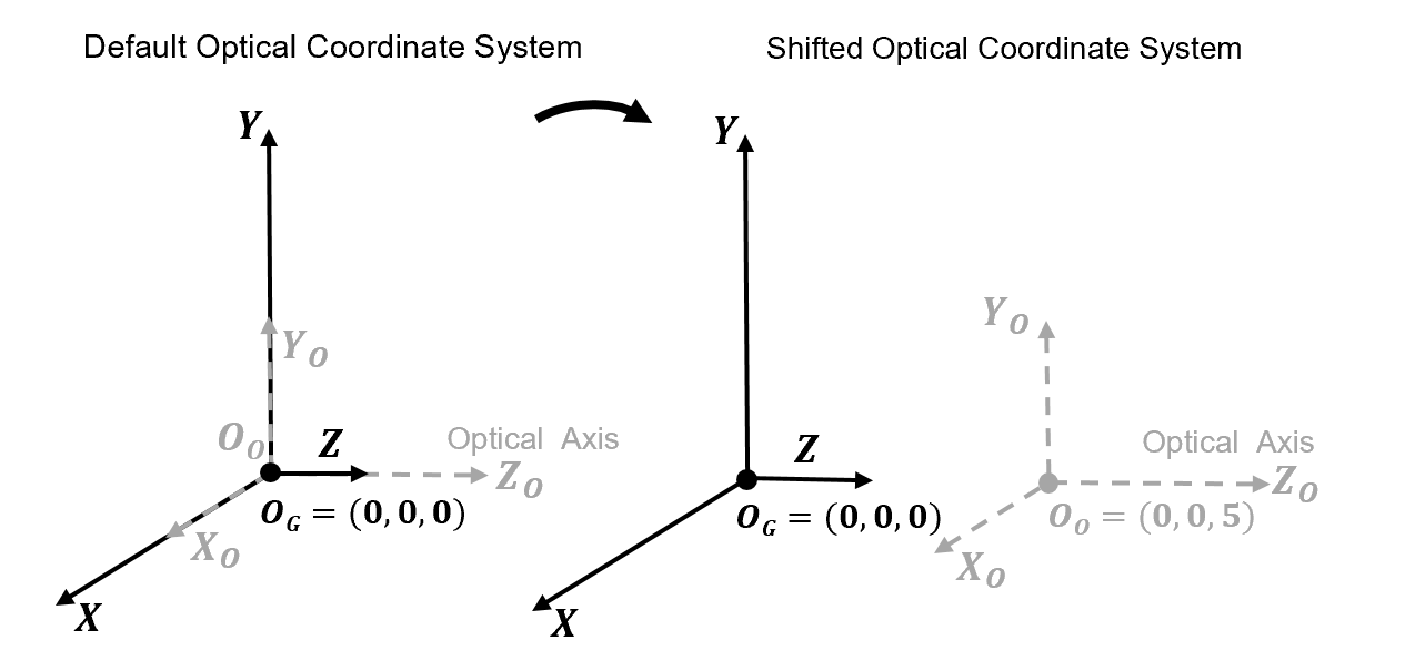
The optical system itself has a local coordinate system which is defined by an origin OO and optical axes XO, YO, and ZO, relative to the global reference frame. The optical axis is the central ZO-axis that typically passes through the center of curvature of the optical elements, and is perpendicular to the image plane and the lens surfaces. This image shows the default position and orientation of the optical coordinate system, and a change in position of its origin as a result of translation in the global Z-direction.
Modify the position and angular orientation of the optical system in these ways.
Shift the origin of the optical system in the global reference frame — Specify the
Positionproperty when you create the system using theopticalSystemobject. This modifies the default location of the first component or surface.Tilt the optical axis with respect to the global coordinate system — Specify the
TiltAngleproperty when you create the system using theopticalSystemobject.
Local Component Coordinate System
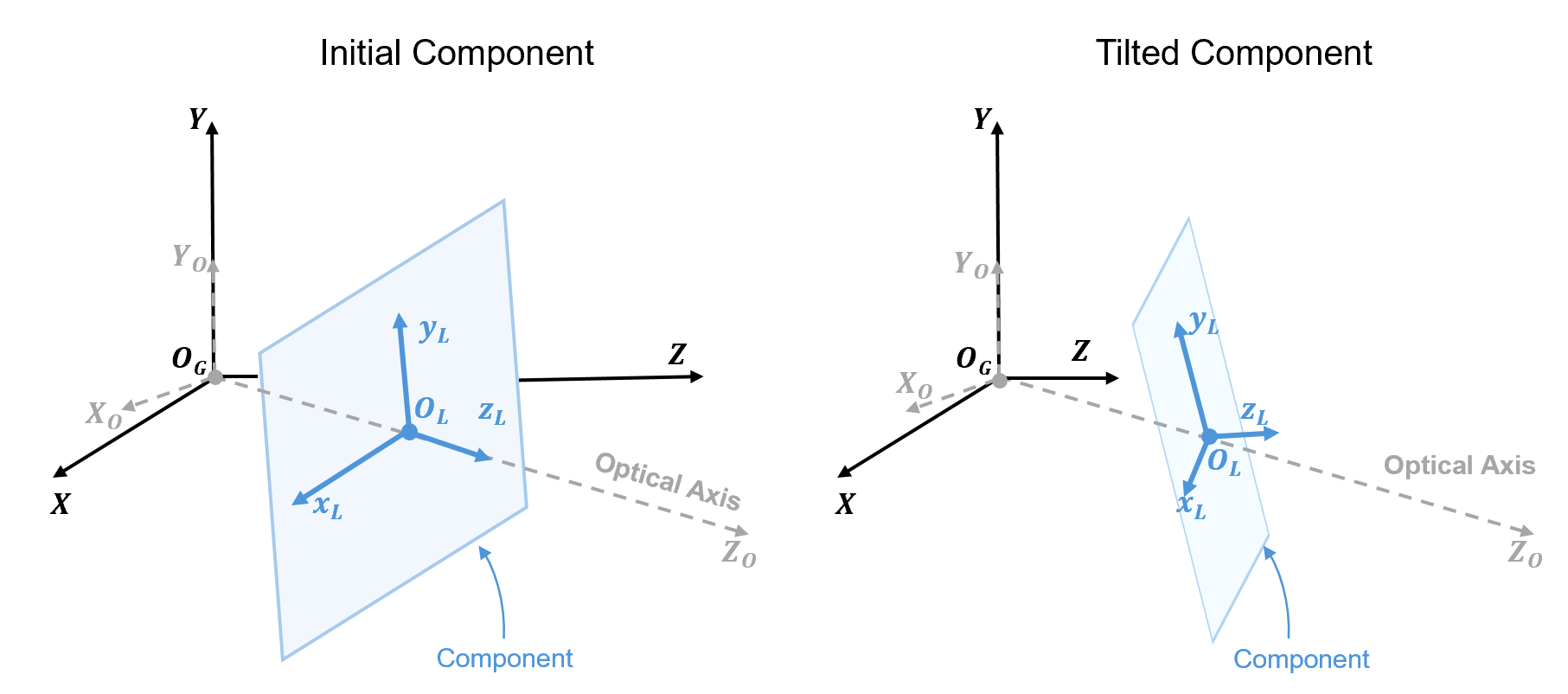
The components of the optical system, which can themselves be nested optical systems, have a local coordinate system that is oriented and positioned relative to the parent optical coordinate system. The default origin of the local coordinate system of each component, OL, is located at a point on the component, such as the first vertex of a lens element. The local coordinate frame consists of three local coordinate xL-, yL-, zL-axes.
This image shows an initial orientation of an optical component on the left, and a tilted optical component on the right.
You can modify the position and tilt of individual components. Tune the position
and orientation relative to the local coordinate frame of the optical system by
setting the TiltAngles and Position
properties, respectively, of the LensElement, Diaphragm, Mirror,
ImagePlane, or ObjectPlane object.
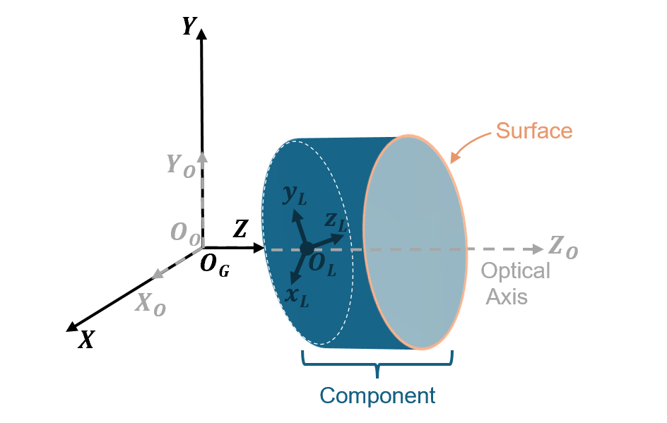
This image shows a representative component that is oriented and positioned relative to the optical coordinate system, and has its own local coordinate system. A surface that constitutes this component has a position and orientation that is relative to its corresponding parent component coordinate system.
Tune the position and orientation of a surface by setting the
TiltAngles and Position properties,
respectively, of the Surface
object.
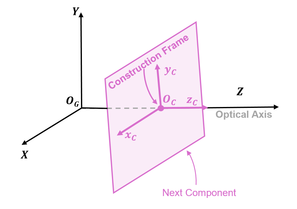
Construction Coordinate System
The construction coordinate system, also called the construction frame, is a coordinate frame that can be used to define the position, orientation, and alignment of the next component or surface in the optical system. The default origin of the construction frame, OC, is located at a central point on the previous component, such as the end vertex of a lens element. The construction frame consists of three local coordinate xC-, yC-, zC-axes. This image shows a construction reference frame whose zC-axis is aligned with the optical axis and the global Z-axis.
When you add a new component or surface to an optical system, you change the origin of
the construction frame for the next component by updating the ConstructionFrame property of the opticalSystem object. The new construction frame origin, or the location
at which the next component is placed, is represented as a 3-D transformation
matrix.
Each element Rij in the first, second, and third rows of the matrix rotates each of the construction xC-, yC-, and zC-axes, respectively, in the global X-, Y-, and Z-directions. The first three elements of the fourth column, Tx, Ty, and Tz, represent the translation of the component's origin in the global X-, Y-, and Z-directions, respectively.
For example, display a sample value of the ConstructionFrame
property of an optical system opsys:
opsys.ConstructionFrame

ans = 4×4
     1      0     0     0
     0      1     0     0
     0      0     1     3
0 0 0 1 Modify Default Coordinate Construction Coordinate System
When you add a new component or surface to an optical system using the addRefractiveSurface, addImagePlane, addDiaphragm, or add
object function, its default position and angular orientation matches the position
and angular orientation of the previous component. When you add a mirror using the
addMirror object function, the default construction frame is
oriented along the reflected optical axis.
You can tune the construction frame for the next component in these ways.
Before you add the component or surface, specify a custom construction reference frame relative to which the component is placed using the
setConstructionFrameobject function. Specify the origin and angular orientation of the new construction frame using thePositionTiltAnglesWhen you add a component or surface using the
addobject function, you can position component in the global coordinate system, or in the current construction frame by specifying thereferenceFrameGlobalorConstructionFrame, respectively.
See Also
Functions
opticalSystem|setConstructionFrame|fieldPoint|addRefractiveSurface|addImagePlane|addDiaphragm|addMirror|Surface|ObjectPlane|traceRays