主要内容

addMirror

Add mirror component to optical system

Since R2026a

Description

Add-On Required: This feature requires the Optical Design and Simulation Library for Image Processing Toolbox add-on.

addMirror(opsys) adds a circular mirror component to the optical system opsys. When you create a mirror component using this function, you create a Mirror object.

addMirror(opsys,Name=Value) also specifies properties of the mirror using one or more name-value arguments. For example, Radius=-50 specifies the radius of curvature of the mirror as -50 millimeters.

example

Examples

collapse all

Create a default optical system and display its properties.

opsys = opticalSystem
opsys = 
  opticalSystem with properties:

   Main properties
                      Name: "Optical System"
         PrimaryWavelength: 587.5618
               Wavelengths: [486.1340 587.5618 656.2810]
               FieldPoints: [1×1 optics.fieldpoint.FieldAngle]
                Components: [0×1 optics.component.Component]
       FlattenedComponents: [0×1 optics.component.Component]
                 Materials: [0×0 opticalMaterial]
                  Surfaces: [0×0 optics.surface.Surface]
              SurfaceTable: [1×0 table]

   Extended properties
                  UserData: []
               ObjectPlane: [1×1 optics.component.ObjectPlane]
    PrimaryWavelengthIndex: 2
           AmbientMaterial: [1×1 opticalMaterial]
                  Coatings: [0×0 opticalCoating]
         ConstructionFrame: [4×4 double]
                  Position: [0 0 0]
                TiltAngles: [0 0 0]

Add a gap using the addGap object function.

addGap(opsys,10)

To add a mirror component to the optical system, use the addMirror function. Specify a tilt angle, using the TiltAngle name-value argument, that tilts the flat mirror 45 degrees clockwise along the x-direction. Specify the center thickness of the mirror, in millimeters, using the DistanceToNext name-value argument. The function automatically adds the specified 10 millimeter gap along the reflected optical axis, which now reflects in the positive y-direction (upwards).

addMirror(opsys,SemiDiameter=4,TiltAngles=45,DistanceToNext=10)

Add another mirror with a tilt angle of the new mirror such that the rays travel parallel to the positive z-axis. This tilt angle is -45 degrees counterclockwise relative to the positive x- axis, starting from the upward-oriented optical axis.

addMirror(opsys,SemiDiameter=4,TiltAngles=-45)

Add a gap between the mirror and the next optical component using the addGap object function.

addGap(opsys,10)

Add an image plane using the addImagePlane object.

addImagePlane(opsys,SemiDiameter=2)

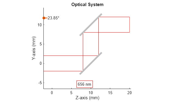
Trace marginal rays through the optical system using the traceMarginalRays function, and display the optical system in 2-D using the view2d function. Add the traced rays to the visualization by using the addRays function.

hv = view2d(opsys);
mr = traceMarginalRays(opsys,Wavelengths=656.261);
addRays(hv,mr)

Figure contains an object of type optics.ui.opticalsystemviewer2d. The chart of type optics.ui.opticalsystemviewer2d has title Optical System.

Input Arguments

collapse all

Optical system to which to add the mirror as the next component, specified as an opticalSystem object.

Name-Value Arguments

collapse all

Specify optional pairs of arguments as Name1=Value1,...,NameN=ValueN, where Name is the argument name and Value is the corresponding value. Name-value arguments must appear after other arguments, but the order of the pairs does not matter.

Example: addMirror(SemiDiameter=3.0) specifies the semi-diameter of the mirror as 3.0 millimeters.

Radius of curvature of the mirror, specified as a numeric scalar. By default, the radius of curvature is 0, which represents a planar surface.

Aspheric coefficients of the mirror, specified as a 20-element row vector. The aspheric coefficients describe the aspheric profile of the mirror. By default, both even-powered and odd-powered aspheric coefficients are equal to zero, and the mirror is a purely conic section without any higher-order deviations. The conic surface shape depends on the magnitude and sign of the conic constant specified by the ConicConstant name-value argument.

Mirror optical coating, specified as an opticalCoating object. The addMirror function applies the coating to the front of the mirror surface where incident rays hit. By default, the coating is a single 200 nm layer of silver (Ag).

Mirror substrate material, specified as an opticalMaterial object. By default, the substrate material is SiO2.

Even-powered aspheric coefficients of the mirror, specified as a 10-element row vector.

Conic constant, specified as a numeric scalar. The conic constant defines the conic shape of the mirror. Depending on the value of the conic constant K, the aspheric mirror surface has these conic shapes.

ConicConstant ValueConic Shape

K = 0

Sphere

K in range [-1, 0]

Ellipse

K = -1

Parabola

K in range [-inf, -1]

Hyperbola

Normalization radius, specified as a positive scalar. The addMirror function uses the normalization radius to non-dimensionalize the higher-order terms in the polynomial describing the aspheric mirror surface.

Mirror semi-diameter, in millimeters, specified as a positive scalar. The semi-diameter is the distance, along the positive y axis, from the center of the mirror to the edge of the usable optical area. This quantity is half the full diameter of the mirror.

Note

For a rectangular mirror, use the RectangleSize name-value argument to specify the mirror surface size, instead.

Version History

Introduced in R2026a