setConstructionFrame
Set coordinate break for all subsequent components in optical system
Since R2026a
Description
Add-On Required: This feature requires the Optical Design and Simulation Library for Image Processing Toolbox add-on.
setConstructionFrame(
specifies a coordinate break for all the subsequent components in the optical system using
one or more name-value arguments. For example, opsys,Name=Value)TiltAngle=[10 10 0]
specifies a tilt angle of [10 10 0] for all the subsequent components
in the optical system.
Examples
Create an empty optical system, and specify the light wavelength as the Fraunhofer F line.
opsys = opticalSystem(Wavelengths=optics.constant.Fraunhofer.F);
Display the value of the ConstructionFrame property of the optical system opsys.
opsys.ConstructionFrame
ans = 4×4

     1     0     0     0
     0     1     0     0
     0     0     1     0
     0     0     0     1
To add a lens component to the optical system, create the first refractive surfaces of the lens. Specify a positive radius of curvature using the Radius name-value argument, the thickness of the lens using the DistanceToNext name-value argument, and the glass material type using the Material name-value argument.
addRefractiveSurface(opsys,Radius=15,DistanceToNext=2,Material="N-BK7")Create the second refractive surface of the lens. To create a convex lens, specify a negative radius of curvature for the second surface using the Radius name-value argument.
addRefractiveSurface(opsys,Radius=-15);
Display the updated value of the ConstructionFrame property of opsys.
opsys.ConstructionFrame
ans = 4×4

     1     0     0     0
     0     1     0     0
     0     0     1     2
     0     0     0     1
Set the coordinate system for the next component. Specify the position of the new construction optical axis as [0 1 5], and tilt the new construction axis by 10 degrees relative to the global x-axis. This configures the optical system to position the next components you add along the specified tilt angle, starting at the point [0 1 5].
setConstructionFrame(opsys,Position=[0 1 5],TiltAngles=10)
Display the updated value of the ConstructionFrame property of opsys.
opsys.ConstructionFrame
ans = 4×4

    1.0000         0         0         0
         0    0.9848   -0.1736    1.0000
         0    0.1736    0.9848    5.0000
         0         0         0    1.0000
Add a second lens component to the optical system, by adding the two refractive surfaces of the lens to the optical system.
addRefractiveSurface(opsys,SemiDiameter=2,Radius=10,DistanceToNext=1.5,Material=pickGlass("N-BK7"))
addRefractiveSurface(opsys,SemiDiameter=2,Radius=-10)
Add a gap and add an image plane.
addGap(opsys,10)
addImagePlane(opsys,SemiDiameter=1)
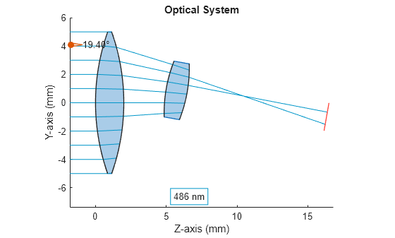
Trace rays through the optical system using the traceRays object function.
rays = traceRays(opsys,SamplingSurface="first-surface");Display a 2-D visualization of the optical system using the view2d function. Visualize the ray path using the addRays object function.
hv = view2d(opsys);
addRays(hv,rays)
Input Arguments
Name-Value Arguments
Version History
Introduced in R2026a
See Also
opticalSystem | addRefractiveSurface | addImagePlane | addDiaphragm | addMirror | glassLibrary